XT Restoration Project - Part 1
Every once in a while do you embark upon a project that you have wanted to do for a long time, but never got around to it. This project is one of those - it involves my very first PC, so I wanted to give it the time and dedication it deserved, and that time is now.
Before we dive into this restoration, a bit of background...
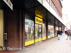
I bought my XT-compatible PC on 14th May 1990 from a store on Tottenham Court Road, London called Morgan Computers. It cost all the money I had: £300. These guys were regular advertisers in PC Magazine and Personal Computer World here in the UK, and I registered with them to post me a flyer once a month (it was called the "Morgan Flyer"). Poring over the cheap hardware deals when the flyer landed in my mailbox allowed me to realise I could get my own PC on a budget. Having grown up with home computers, the move to a PC was a natural progression. Morgan Computers' unofficial mantra was "pile 'em high, sell 'em cheap" - they sourced old stock from businesses en masse or from liquidations, and sold them on at close to wholesale prices. Around the start of 1990, like so many other computer companies, they jumped on the PC clone bandwagon: making and selling brand new PCs under their own brand, ranging from the humble XT up to 386DX-25s with colour SVGA graphics. Morgan is still going strong today, though it changed hands back in the early 2000s.
I had spent the months before saving hard and deliberating over whether this computer was the best choice compared to the similarly-priced Sanyo MBC-555, and a myriad of the other XT clones around at the time. I soon put together my key buying checklist:
- Under £300 (about $500 USD in 1990)
- 640 KB of RAM
- 8 MHz minimum
- Expandable
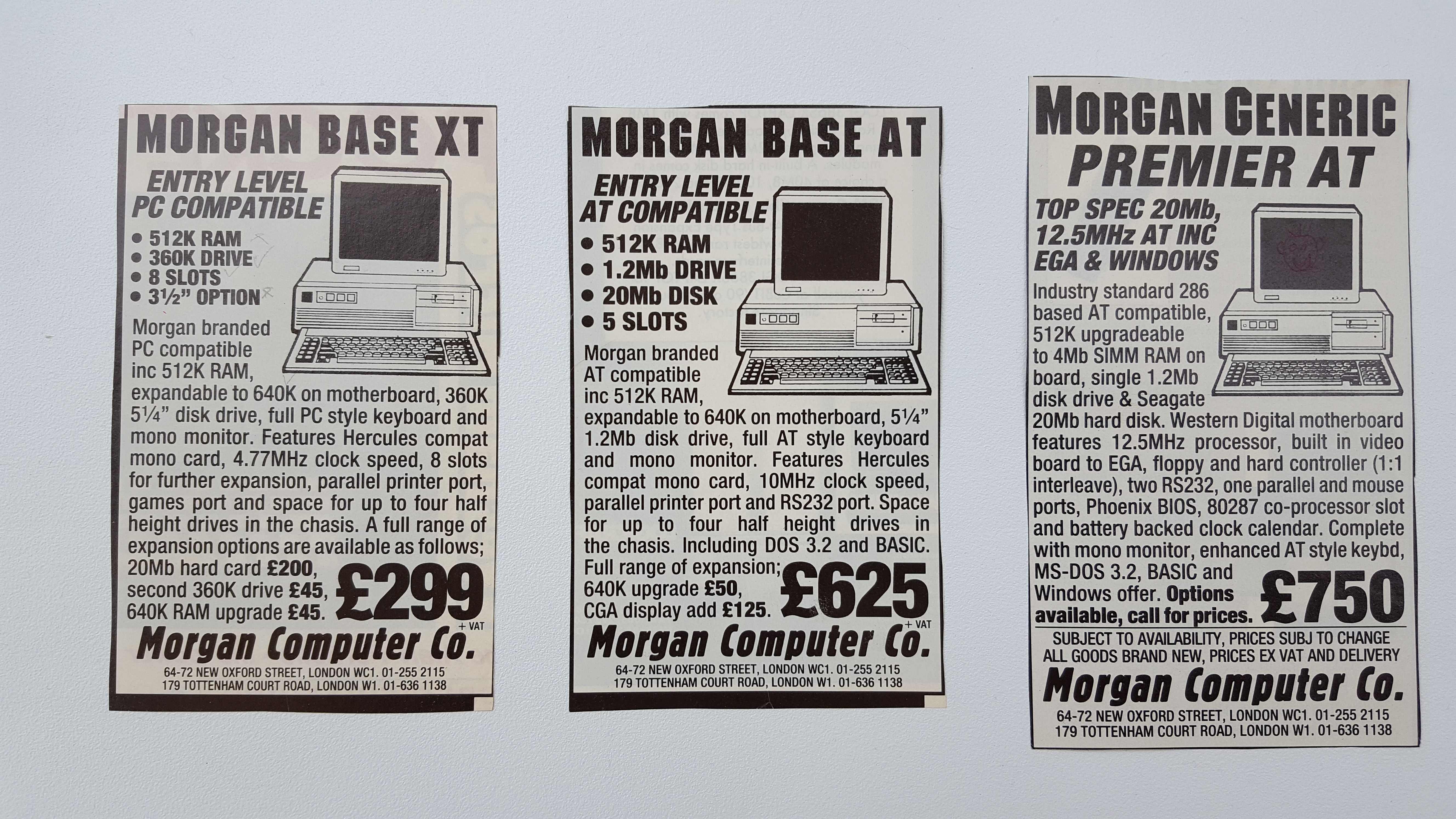
Adverts from early 1990 for the Morgan PC range
As I mentioned, I had very little money in 1990. I had yet to get a part-time job and was still in school, so this was pocket money savings, but still, I had managed to save just enough for a new computer. The PC market was aggressive - prices fluctuated massively with known companies like IBM, Compaq, Viglen, Dell and Olivetti to name but a few leveraging their "premium brand" status against hundreds of lesser-/unknown-brand competitors looking for ways to undercut them - and they did, massively! This was a time when you really could say "Why should I pay $3,000 for a Compaq when Brand X has the same-specced computer for a third of that?" And it was the same in the UK. The discerning personal computer buyer had wised up.
A cheap, no-brand 286-based PC would typically set you back £700 and for a 386 around £1,200. At these prices it would come with a 20 MB hard disk, Hercules monochrome display card and a 12" mono monitor. Upgrading to colour CGA would add £150 to £200 to the price tag or to get colour VGA it was more like £500 more.
But my sights had to be lower. Around the £300 mark there was a lot of choice as manufacturers tried to get into the home consumer market - Schneider Euro PC II, Sanyo MBC-555, Atari PC3, Commodore PC-1, Zenith Eazy PC 1 and a good few more were on my shortlist.
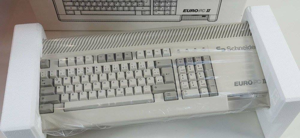

From left: Schneider Euro PC-II, Atari PC3, Commodore PC-1, and Zenith Eazy PC 1
Incredibly in 1991 there were still PCs that were *not* 100% IBM-compatible - the interpretation of what that means has changed over the years, but back then it came down to whether the machine could boot into DOS, run Lotus 1-2-3 and play Microsoft Flight Simulator (I'm oversimplifying here but these were literally some of the things that were done to check for a PC's IBM compatibility). Some examples: the Tandy range whose audio and display circuitry differed from the IBM standards, Apricot PCs as I recall had floppy drives that used a different format/capacity, and the Zenith Eazy PC had an 'option' slot instead of standard ISA slots.
The Sanyo was particularly interesting - I think their marketing team were great at what they did - a good-looking computer in silver and black to not look out-of-place beside your home Hi-Fi, and it came with two floppy drives, but further investigation warned me off - it was a world away from being "IBM compatible" - it didn't have a DMA controller and common applications had to be compiled specifically for them to work on an MBC-55x - even the DOS 2.1 (!) that it came with was a special version just for the MBC-555. The Schneider and Zenith were much more compatible with an IBM, so you could run almost all PC software on them, but they weren't really upgradable. The Commodore PC-1 only ran at 4.77 MHz and the Atari PC3, well I honestly forget why this was ruled out - most likely slightly over my price point, So I eventually decided to buy the Morgan Generic Base XT. And I should mention that despite the advert above putting its clock speed at a miserly 4.77 MHz, that wasn't the ad that drew me to the Morgan PC (that must have been an earlier one) - the one I recall seeing had it running at 8 MHz, and at the time I was ruling out anything slower like the Commodore.
I worked out that if had bought all the parts separately the cost breakdown would look something like this:
- 8088 motherboard: £45
- 640 KB RAM: £30
- 5.25" 360 KB floppy drive: £45
- 12" Philips monitor: £72
- Hercules graphics card: £25
- 102-key keyboard: £55
- Case and power supply: £50
Total: £322. So it made sense to get a budget pre-built system rather than building one myself from component parts. The concept of a "self-build" just didn't exist back then for the average user. No adverts sold a PC case separately, or a power supply, though you could buy a memory upgrade, or an EGA or VGA card, or a 3.5" floppy drive. These were the years when you bought a base system, and then invested more later on to upgrade it, and the media advertisements reflected this philosophy.
A few things were different about the Morgan Computers advert above to what I bought. The system I got was a 9.54 MHz unit with 640 KB of RAM. There must have been a fortunate change in specification just before I bought it, as I knew when I called them to buy it that I was getting a fast XT with 640 KB. But it also came with serial and parallel ports and a real-time clock on its 'Multi I/O' card. The only software I got was a 5.25" 360 KB floppy which was an original Wyse MS-DOS 3.21 - I vaguely recall even having to ask them to bundle it with an OS!
30 years on, I can safely say it was a good deal. During its useful life the only issues I had were the Seventeam ST-150 power supply going belly up (repaired by an electronics friend of the family) and a trip back to Morgan Computers after just 2 months for a faulty 5.25" floppy disk drive (the diagnosis reported was poor head alignment).
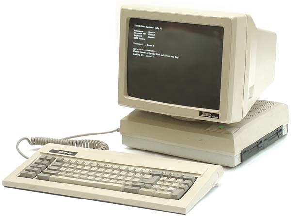
The motherboard of the Morgan Generic Base XT is probably the most tightly-integrated you have ever seen. It measures just 220mm x 150mm (11" x 8"), so it was dwarfed by the IBM PC/XT-sized case it came in, along with a single 5.25" 360 KB Mitsumi floppy disk drive and a 12" Philips green-screen monitor. The only expansion cards were a multi-I/O card (floppy disk controller, serial and parallel port), and a small Hercules-compatible graphics card.
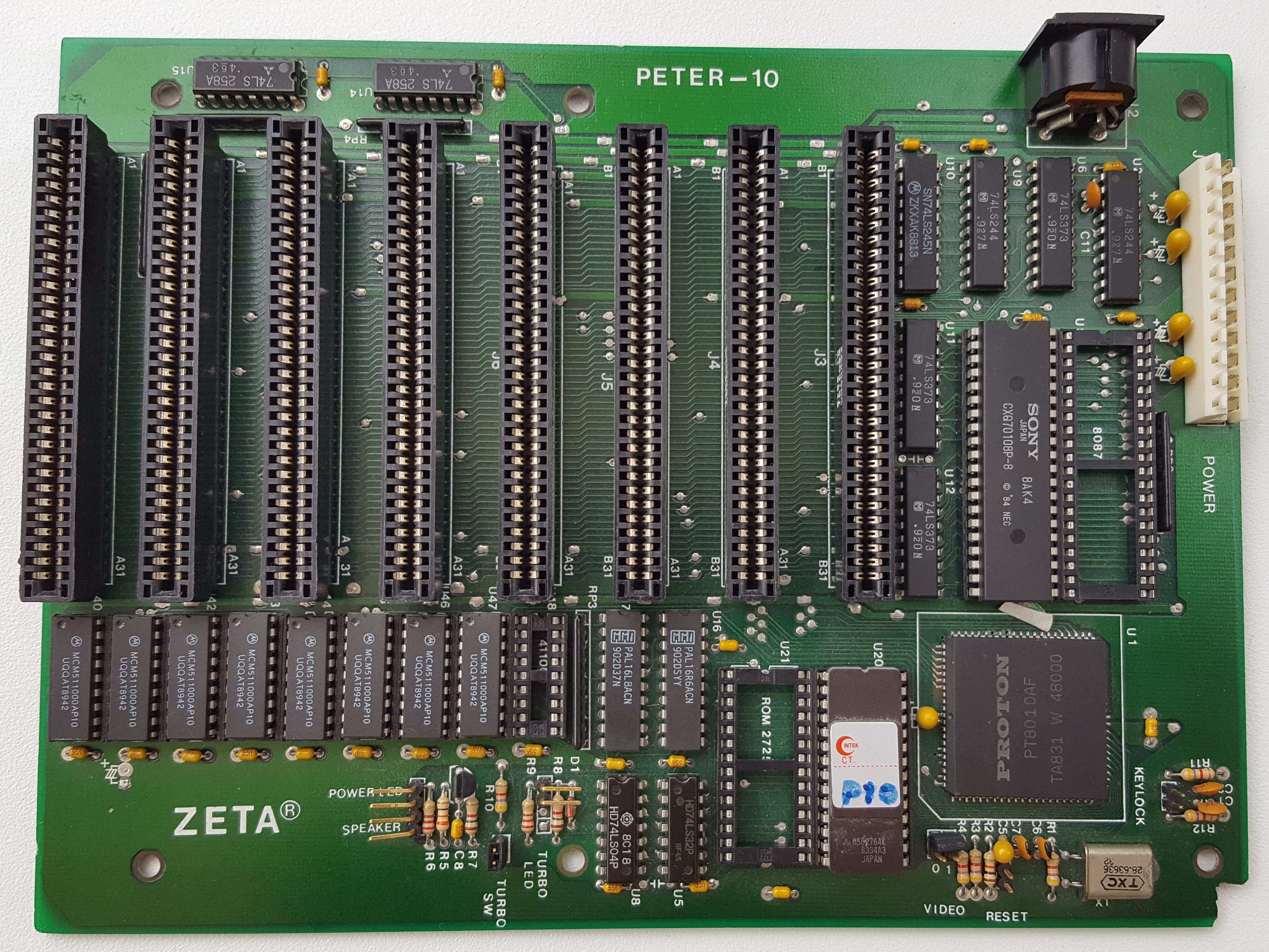
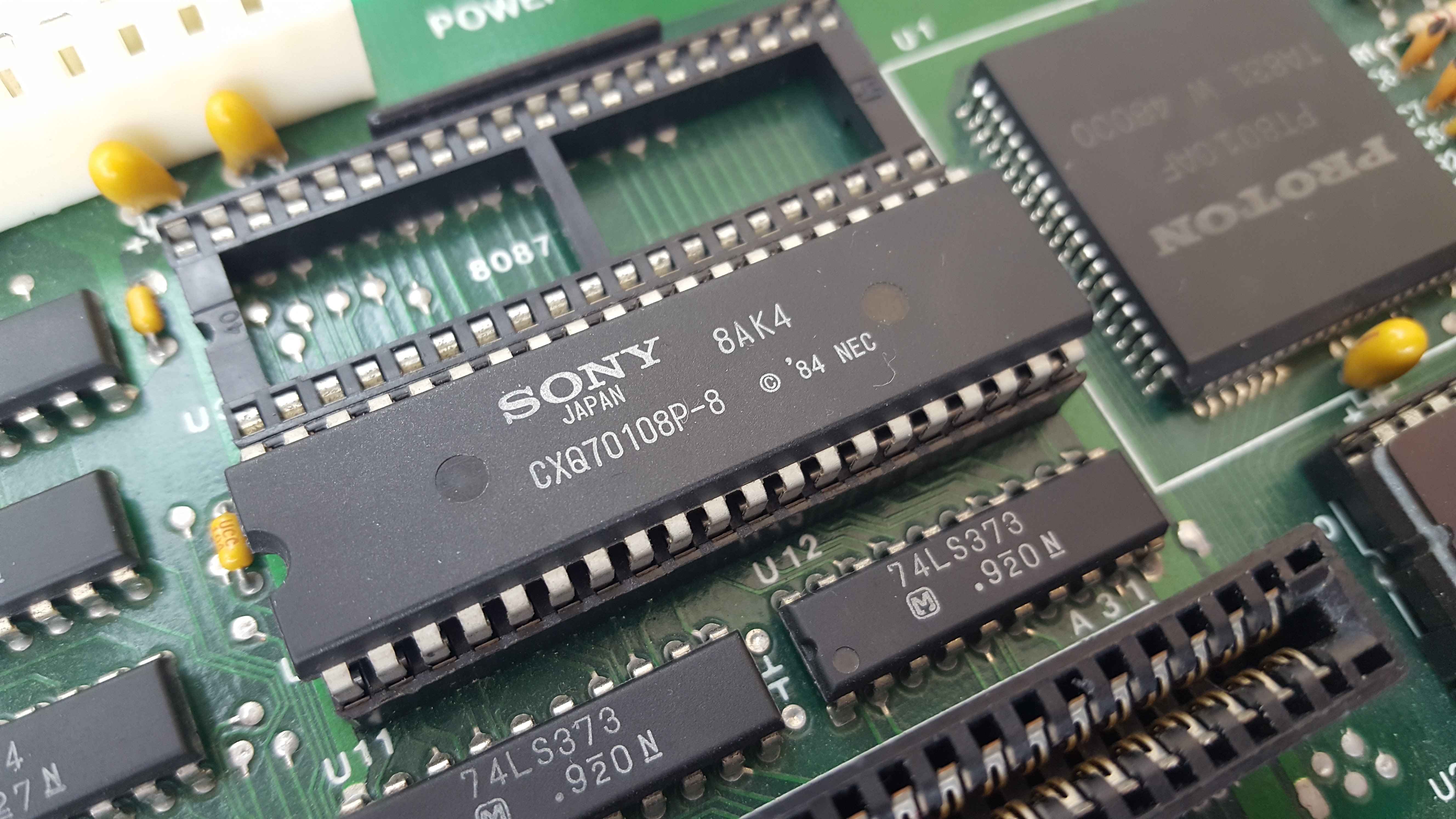
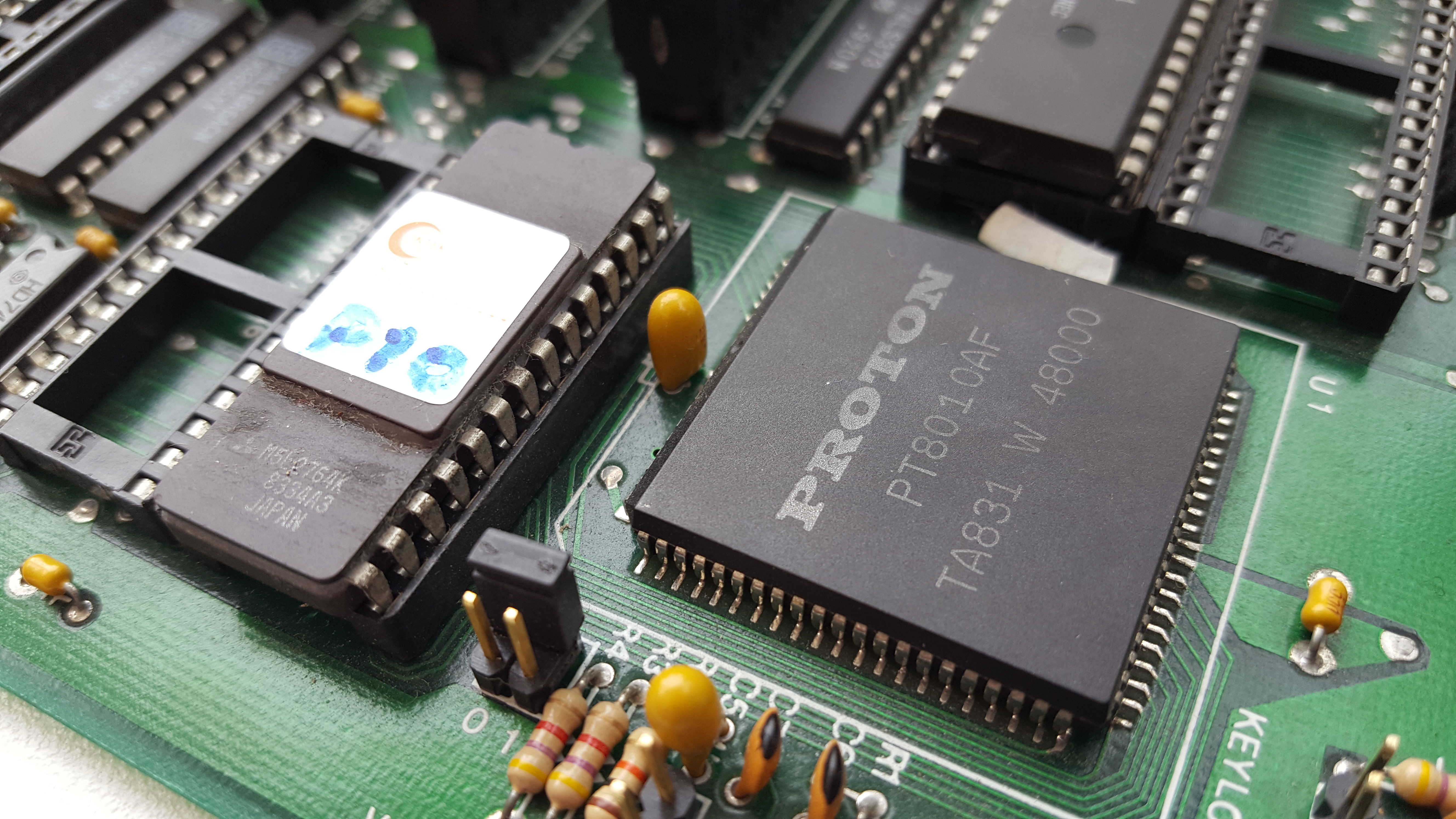
On the motherboard itself there are just 15 chips plus 8 more for the 640 KB of RAM. This is made possible due to the large ASIC which is a Faraday FE2010A - an XT chipset that handles the majority of tasks a motherboard has to do, such as controlling the bus, interrupts, DMA, keyboard, etc. On my specific motherboard this ASIC is branded Proton PT8010AF but under the hood it is the FE2010A.
The computer came with a Sony-branded NEC V20 rated at 8 MHz.
The single BIOS chip is one I have never heard mentioned anywhere else. It's a ZETA P-10, which matches up with the name on the silkscreen which reads "PETER-10". The 10 is because this is a 10 MHz PC; well ok, 9.54 MHz (which is 4.77 MHz x 2, or CLK / 3 - the crystal runs at 28.636 MHz), but the magazine adverts usually took a chance and rounded things up. The turbo button drops this down to 4.77 MHz. So the CPU rated at 8 MHz is being overclocked by about 20% - bravo Sony.
One key advantage of a board like this, looking at it almost 30 years on, is that being such an integrated design means its reliability was excellent. This was the whole purpose behind chipsets! Well OK, cost reduction was the key driver, but they sold them to PC builders on the basis of vastly improved reliability over dozens of smaller ICs and 'glue logic' doing the same task.
But even compared to the early chipsets from C&T, VLSI and G2 (Headland) that were rather sensitive to ESD (electrostatic discharge) or overclocking, where any one of 5 chips in the set could suffer a fault; this little single chip is a thing of beauty. It does everything inside one chip, and it just works - sadly it probably came to market too late to really make an impact.
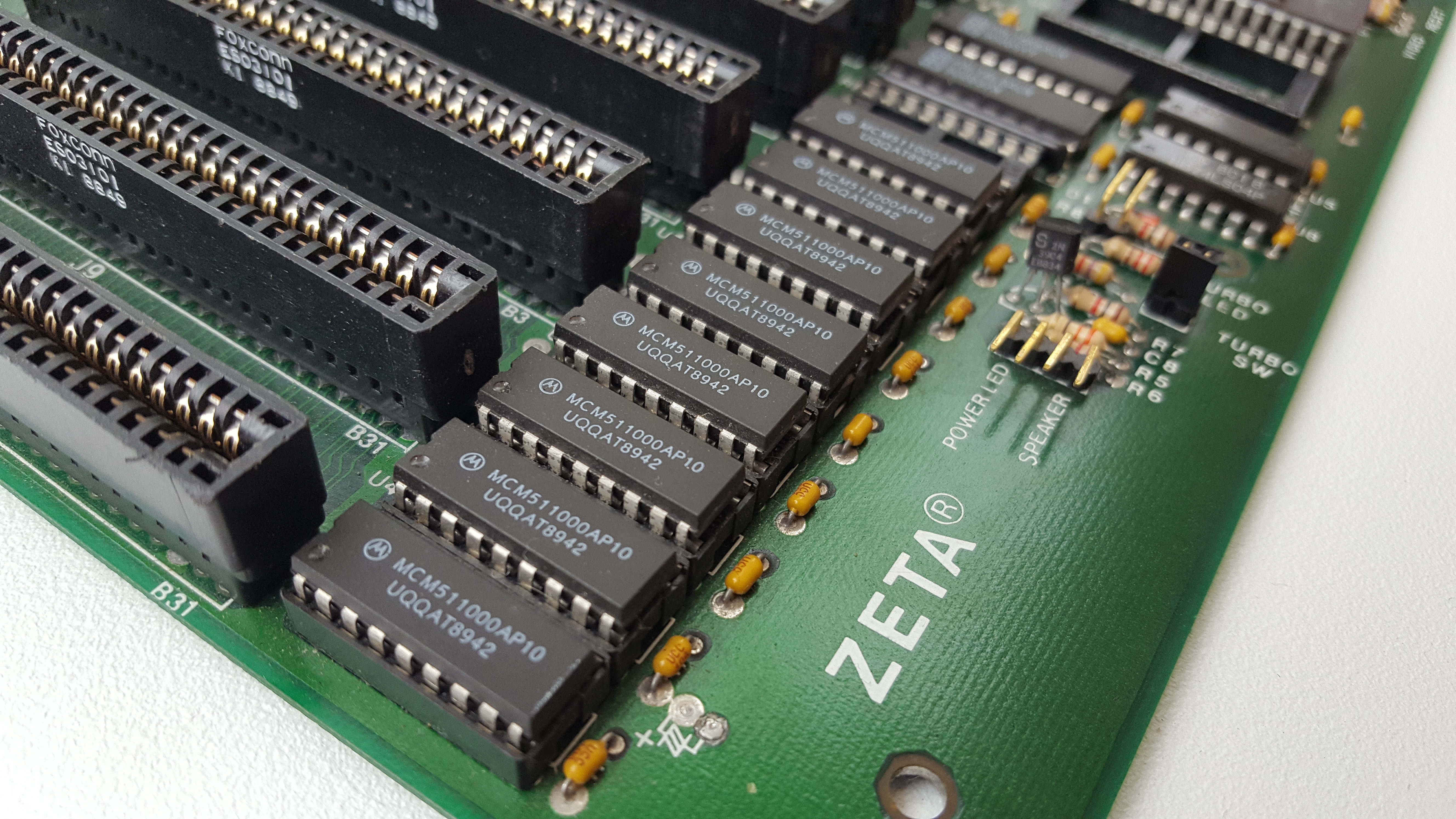
The ZETA motherboard came with a full 1 MB of RAM chips (8 x 128 KB Fast Page Mode (FPM) 100ns DRAMs), although the chipset limits what is usable to 640 KB. It has a socket for an 8087 math co-processor as well as a second ROM socket - two expansion options that are on almost every XT clone's motherboard but were rarely used.
One very nice thing that came with the Morgan was the keyboard - an ITT-branded 'Enhanced' 102-key keyboard that had an XT/AT switch - this was being advertised individually by Morgan for £55, odd to think the keyboard alone was almost 20% of the cost of the whole computer!
I'm not sure what I did with the original Hercules-compatible graphics card. I managed to upgrade to an EGA card and monitor several years later (1992?) and eventually to SVGA. The monitor that came bundled with the PC was the very reliable Philips "Computer Monitor 80" (model BM7513) which output green phosphor. The almost-identical BM7523 was the amber version. It was common around the mid-to-late 80s to get either an amber or green monitor as it was discovered these colours resulted in less eye strain compared to black & white when working with text applications. I always loved the look of the amber ones - some PC advertisements even stated what 'colour' the mono output (white, green or amber) was. With Morgan, it was whatever they had got a deal on so you never knew what you'd end up with - I even called them to ask if I could get an amber monitor instead!
At the time a lot of games required CGA as a minimum graphics standard, which was a shame given that the Hercules resolution was so much higher (720 x 348 compared to 320 x 200 or 640 x 200), though Hercules lacked the 4 colours - well, any colours!
A small sample of CGA graphics (click to expand)

...and here are some Hercules graphics games (click to expand)
Hercules had normal, intense, underline and flashing as the only attributes for its text, so not too good if you're a game developer. But to be clear, it was never designed with that in mind. Its high resolution was for the purpose of clear high-resolution text display for word processing and spreadsheet work, with the most graphics demand being to draw a bar or pie chart on the screen.
The answer to achieving CGA for games for us poor folks who only had Hercules cards was to use what were called "CGA simulators". The ones I used in the early 90s were HGCIBM and occasionally SIMCGA. If you're interested in diving into this topic more, go over to my CGA Simulators page. Before starting the game I would run a CGA simulator and it would do the translation of BIOS video calls to allow me to play colour CGA games on my Hercules graphics card and monitor, albeit in 4 greyscales (green scales?) or using dithering to approximate multiple shades.
Despite the fact that these early PC clones were not powerful and looked fairly bland, there was this overwhelming sense that you had entered the 'professional' market with a PC regardless of what CPU was inside. From 1982 my family had a home computer - we started with a ZX Spectrum, then moved to a Commodore 64, and later to an Amiga. Great machines, full of vibrant colour and entertainment value. But I now had a 'business' computer. In 1990, I 'had' to have a word processor. I 'needed' a spreadsheet. But I also wanted to still play games. The latter, sadly, would take time to build up funds to upgrade to colour, to a faster processor, to a hard disk, but yes! I had a computer and it ran Word Perfect 4.2, Quattro and Turbo Pascal.
So there we are - an IBM PC/XT-compatible with a green screen monochrome monitor, no hard disk, and about 20 floppy disks. Let's shift back to present day, and see if we can get this thing going again!
~~~~~~~~~~~~~~~~~~~~~~~~~~~~~~~~~~~~~~~~~~
As a temporary replacement for my mislaid ITT keyboard I will be using this IBM AT keyboard with an AT2XT converter:
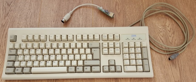
It's no 'buckling spring' Model M, but it's solid and works very well
The converter (top of pic) is one I bought off an Ebay seller for £15 about 6 months ago. You can make these fairly easily if you have rudimentary soldering skills and a bit of veroboard (check the Vintage Computer Forums page here for details). The PIC used is a PIC12F629 and being a PIC it needs to be programmed. I decided to buy mine ready-made, and it works great with any AT-compatible keyboard. Since my XT motherboard has a full-sized DIN socket I also use a PS/2 to DIN adapter since this AT keyboard is from an IBM PS/2 computer.
Problem No. 1 - Keyboard error
My first and main problem is with the motherboard itself. Just a couple of years ago I pulled it out for a routine check-up, and for the first time it told me it was unwell. It appears that now, any XT keyboard I connect to it fails on POST with the message "Keyboard error" right after the RAM test. The system goes on to boot, but will not accept keyboard input at all.
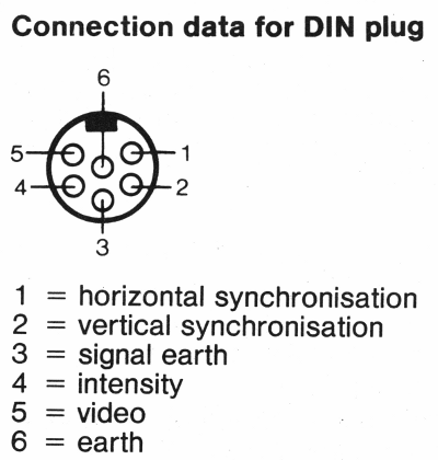
Let's look at the pinouts for the keyboard socket...

5-pin DIN 180° (DIN41524) FEMALE at the computer.
and here are the pin descriptions:
| Pin | Name | Description |
|---|---|---|
| 1 | CLK | Clock - this signal is sent from the keyboard to synchronise the data signal. |
| 2 | DATA | Keyboard scan codes are sent from the keyboard to the computer on this single wire serially. |
| 3 | /RESET | This signal is rarely used and many keyboards don’t even connect it. It was used to let the computer reset the keyboard. |
| 4 | GND | This is a common ground signal used as a return path for data and is a reference to logical 0. |
| 5 | VCC | This is a simple 5 volts signal for giving power to the keyboard. |
I started by tracing each pin from the back of the keyboard connector to where they go on the motherboard:
Pin 1 (CLK) - Goes to one of the 2 Keylock pins.
Pin 2 (DATA) - Goes to a capacitor
near the keylock pin and also goes to pin 26 on the PT8010AF, which is KBDA (Keyboard Data). The other side of the keylock circuit then goes to pin 25, KBCLK (Keyboard Clock signal).
Pin 3 (RESET) - Not connected to anything.
Pin 4 (GND) - I have continuity between this pin and the GND pins on the P8 and P9 connectors (pins 4, 5, 6, 7 and 8). Note that on this mobo, another fault I've noticed is that the -12V pin 4 (blue) on P8 is shorted to GND, so I'm having to run it without the blue wire connected from this other PSU into the P8 connector pin.
Pin 5 (VCC) - I have continuity between this pin and pin2 (+5V) on the P8 connector - good.
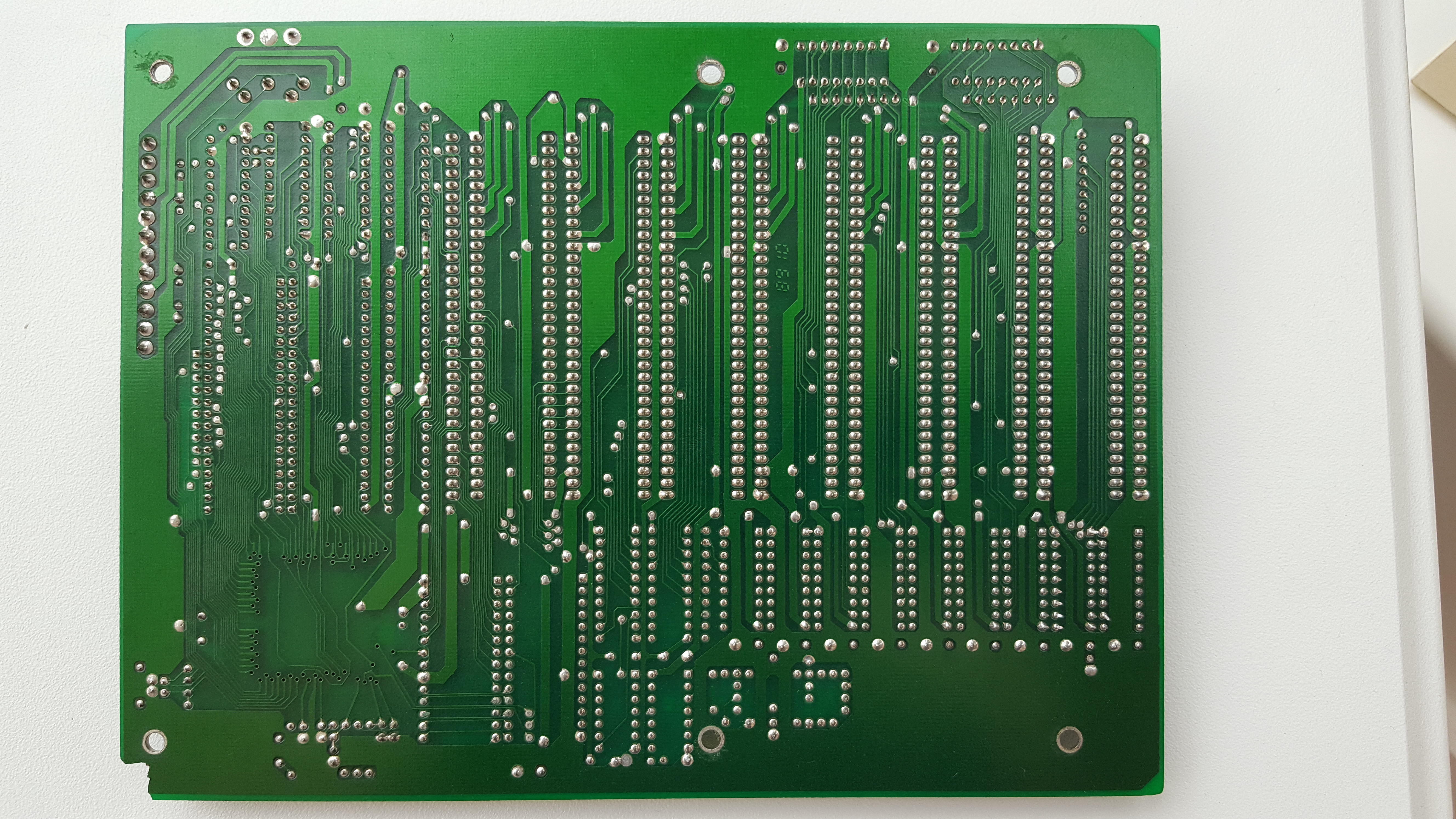
I've checked the circuitry and not found any problems. All pins from the 5-pin DIN keyboard connector go to respective solder pads elsewhere on the motherboard. Two of the keyboard pins connect to legs on the PT8010AF. I'm starting to think this motherboard is possibly a 3- or 4-layer board, not just 2 (top and bottom), as some pins seem to go nowhere but further checks return continuity elsewhere.
In light of the fact the keyboard is getting sufficient power, I have checked the values of any capacitors and resistors along the path of the two signal lines (CLK and DATA), and...
Problem Solved! This is a little embarrassing... if the motherboard were in its original case with the front panel wires all plumbed in, what would be connected? The keylock! I checked the front of the case and sure enough it was in the locked position - by default an open circuit means the keyboard is in the locked position and a somewhat ambiguous "Keyboard error" message will appear on the screen (the motherboard doesn't get a CLK signal passed back to it due to the open circuit). Once I bypass the keylock circuitry the error disappears!
OK, so back on with the build. I don't have my original Hercules graphics card in my collection. For now, I will dig around in my vintage ISA video card pile and see what I can find for a suitable replacement...
.jpg)
A Twinhead CT-6040T Hercules-compatible card with parallel port
.jpg)
A Kouwell KW-526K Hercules-compatible card with parallel port
Either of these will do the job. The Kouwell has slightly faster video RAM (100ns over 120ns) and is more integrated with its TD3088A chip. I paid about £18 for each of these over the last 7 years - prices for ISA cards have been going up due to rarity, so I'm pleased that I gathered together a few here and there while prices were reasonable.
Problem No. 2 - Monitor not displaying an image
My original Philips monitor is showing nothing but a garbled mess that is racing up the screen. I guess 25 years in a loft would do that to most of us, though it's reassuring to see something being displayed.
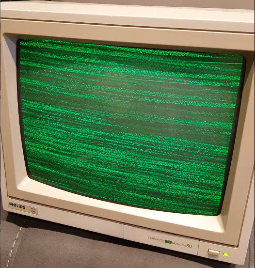
I messed around with the signal cable at the back and it would briefly show almost readable text, though still moving up the screen. Adjusting the vertical hold knob on the back of the monitor fixed the vertical scrolling issue. As for the intermittent display, the fact that moving the cable around a bit temporarily fixes the problem means this is definitely a cable fault, not an issue with the monitor.
For a Hercules monitor such as this the signal is digital TTL (Transistor-Transistor Logic), meaning signals are sent as either "high" (+5V) or low (0V). The cable is a 9-pin male DSUB on the computer end to a 6-pin male round DIN on the monitor end. I dug out the pinouts for the cable, which on the DIN side are:
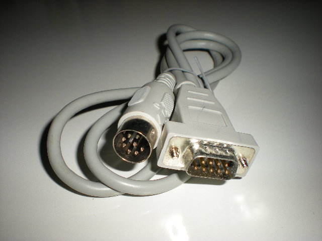
and on the 9-pin DSUB side are:
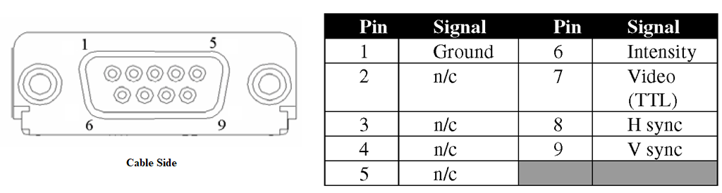
Using a multimeter I have checked continuity between the various pins on both ends of the cable and found that the video wire is almost disconnected. Unscrewing the DSUB end is easier so I've looked in there and it all looks good. Getting into the DIN connector is a pain as it's covered in a tight rubber sleeve. I could just buy a replacement cable but where I can I really want to use as much of the original gear as possible, including cables.
Long story short, I've resoldered the video pin (pin 5) inside the DIN cable and we now have a nice stable picture:
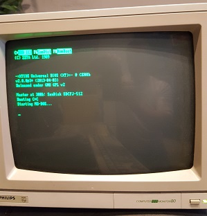
I have plugged in my XT CF-Lite card into one of the expansion slots along with a CF card that's been formatted to FAT16 and boots into DOS 6.22, so I now have a booting motherboard with a working monitor!
SLIGHT TANGENT...
Given my nostalgia with this particular machine, I would like to take a backup of some of the BIOS firmware: specifically the P-10 BIOS and also my favourite old-school Eagle II SVGA card, the "almost full-length" Cirrus Logic CL-GD510/520 with its nice-looking font - the motherboard and VGA card were together from late 1990 when I convinced my brother to sell it to me. Looking back, it's graphics performance wasn't great, but it really didn't factor in, and remember this is before we had even 2D-acceleration let alone 3D, so what VGA card was fast back then? The Tseng Labs ET4000 takes that trophy, but what Cirrus Logic excelled at was hardware emulation - you could set it to be an MGA (HGC), CGA, EGA or VGA card using the EAGLE.COM utility (or even AUTO mode where it would detect the signal and adjust accordingly), and 100% of software could not tell the difference - true hardware register-level compatibility. You could also force its startup mode using the 8 DIP switches on the rear faceplate. I also liked that their MGA mode was amber when displaying on a colour monitor :-)
Anyway, I digress...
BACKING UP the ROM BIOS
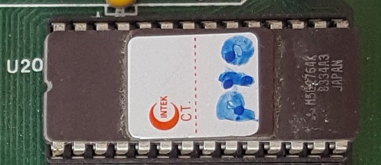
Oh yes, the ROM BIOS... on this motherboard the ROM chip is a Mitsubishi Electric-branded 2764 EEPROM (M5L2764K), which means it's just 8 KB in size.
I'm going to use a utility called PCJRCART.EXE which was written to dump an IBM PCjr ROM, but it works on any PC - you just need to specify the starting memory location and length, or choose the built-in option to dump the System ROM. I chose the latter which created a 64 KB file from the typical BIOS memory location of F000:000. Now I know my BIOS is only an 8 KB EPROM, so I will use a hex editor to locate the actual BIOS code within that file and extract it into a new 8 KB .BIN file. There are numerous "BIOS Dump" utilities out there, and some of the better Diagnostic programs of the day such as QA Plus Pro would also have this option built-in, so choose what you like and trust. You can even use the venerable MS-DOS DEBUG.COM program to extract the contents of memory to a file - this too is just as effective if you know what you are doing.
My aim here is that I don't want to erase and reprogram the P-10 BIOS chip I currently have since it's so old. Rather, I want to dump its contents to file, burn it to a new chip and confirm the new chip works. For this, I need an EEPROM programmer and a spare 2764 EEPROM chip. I don't currently own an EPROM/EEPROM programmer but have used them in the distant past. It's not rocket science to move from software to firmware, and I have some experience of this from my days working on Psion HC industrial handhelds for IBM ServicePoint back in the late 90s - I would just put a "DataPak" under UV light for 30 minutes (an "EEPROM eraser") to erase it, dump my program to it and it would then run on the handheld device. The challenge back then was cramming everything you needed into just 16 KB!
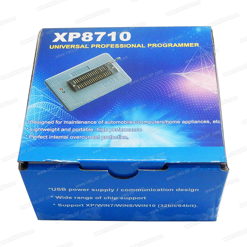
But which burner to buy? Using the Mitsubishi EEPROM's datasheet, it says that to enter programming mode the EEPROM programmer must pass 21V into the VPP power supply input pin on the chip. Looking around at the EEPROM programmers available the most common is the TL866 II Plus, but its maximum VPP voltage is 18V - no good. Its predecessors, the TL866A and TL866CS both supported a VPP of 21V. So their latest product no longer supports the older chips. It's possible I guess to find a more modern replacement EEPROM that requires less than 21V, but a lot of manufacturers EEPROMS have slightly different pinouts, meaning I would need to do some board rewiring too - not fun. Looking at equivalent burners, I have ordered an XP8710 as it's cheap, supports up to 21V for programming and supports 27XXX memory chips.
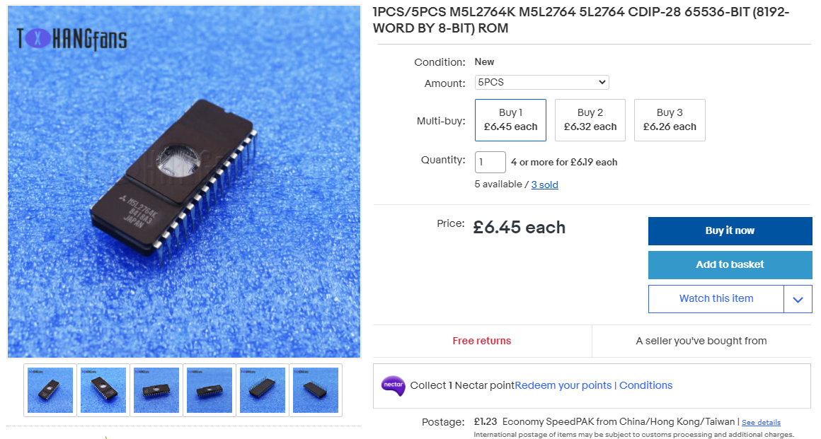
I have also ordered five M5L2764K EEPROM chips - a total of £7.68 delivered which works out to be £1.54 per chip - not too bad if they work.
Regarding the ROM BIOS itself, I don't have any frame of reference for this particular ROM's code - if this were a common IBM 5160 ROM I would get a checksum from the dump and compare that to someone else's .BIN file to be sure there's not a difference in the code or some corruption during the burning process. Fortunately the burner software does have a Verify mode to confirm the code on the chip now reflects the code you loaded.
OK, it's time to take a pause as I wait for the parts to arrive, but while we're waiting join me in Part 2 where I will turn my attention to the case and the original floppy drives.