Retro Review: Yamaha Audician 32 Plus - Part 1
25th January 2023
This week my retro review looks at another sound card that has been in my collection for about 5 years. It is based on the reference design of the Yamaha Audician 32 Plus, and has the Yamaha YMF718E-S at its heart, giving it Sound Blaster, Sound Blaster Pro and WSS compatibility.
.jpg)
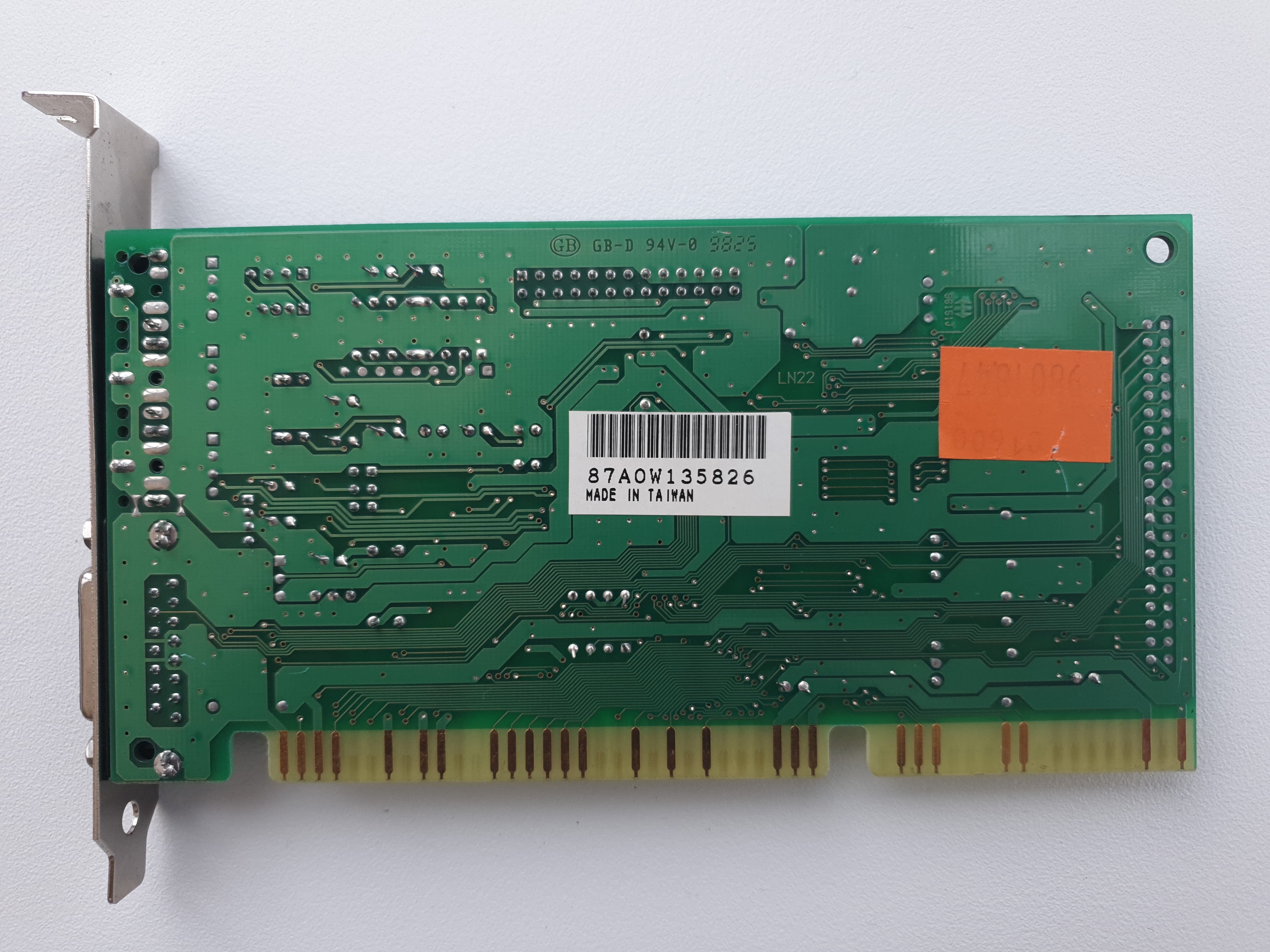
Labway/Addonics-branded Yamaha Audician 32 Plus
Bought in June 2017 for £10
These are very cost-effective sound cards with excellent audio quality, low noise, and great DOS compatibility. The YMF718E-S and YMF719E-S were the last Yamaha audio chipsets for ISA-based sound cards before they moved to the YMF-720 which was PCI-based.
I also have a second Audician 32 Plus that has the YMF719-ES (OPL3-SA3), one that is the same as the Philips PCA750AF shown on my Yamaha page but is actually an A-Trend ATC-6631. Near-identical cards also exist, including the AOpen AW-719, and others from Genius and ACorp.
** UPDATE 28th April 2025: I managed to source one of these cards with the onboard wavetable. Parts 3 and 4 now include the Windows installation and wavetable recordings **
Quick Visual Inspection
Looking around the card, it's a very simple design given that almost everything is handled within the Yamaha chip:
- Yamaha YMF718E-S, aka OPL3-SA2
- Atmel 747 - a toggle switch to control electrical loads (probably to protect the YMF chip)
- ST Microelectronics TEA2025B - stereo audio amplifier
- Wavetable header
- Pads for an AdMOS QDSP QS1000 onboard wavetable and its associated 1 MB ROM chip
- Two crystal oscillators
- Two white 4-pin headers for CD Audio-in (J11) and Mic-in (J13)
- One 4-pin header at J10
- Two jumpers at JP1
- Pads for a 40-pin IDE header
- Faceplate with Mic-in, Line-in and Audio Out 3.5mm jack sockets and 15-pin game/MIDI port
Date-wise, the most recent date stamp on the card's chips is week 10 of 1998, so it was certainly no earlier than March 2nd 1998 when this particular card was manufactured.
The Component Parts
The Yamaha YMF718E-S
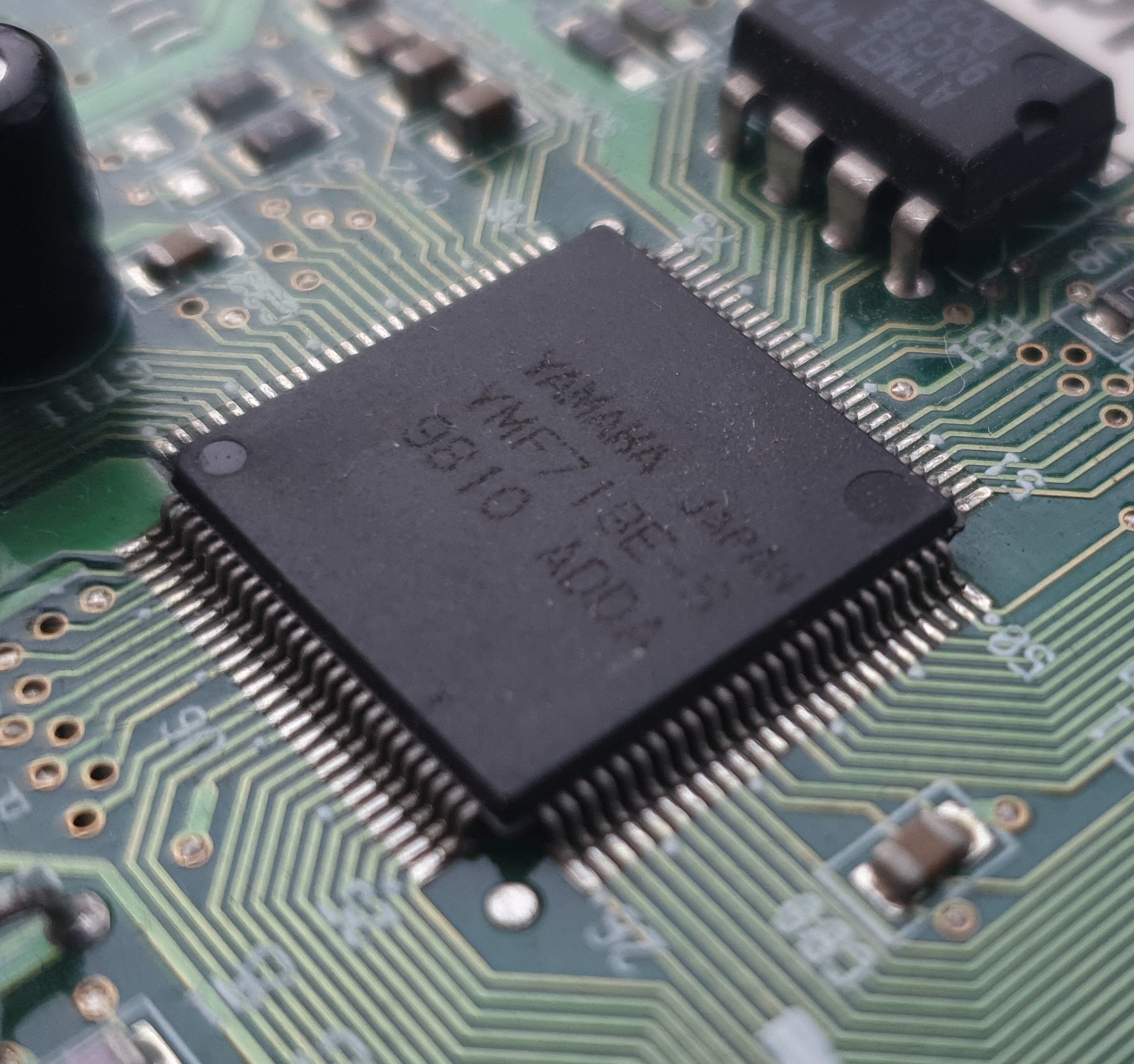 Known also as OPL3-SA2, its key feature addition over the original OPL3 was ISA Plug & Play, and over the earlier OPL3-SA this one added CD-ROM (IDE), modem and zoomed video interfaces. It did *not* come with the 'virtual' 3D audio which Yamaha called Ymersion - that only arrived with the OPL3-SA3 (YMF719E-S).
The successor to the OPL3 range was Yamaha's PCI-based range, starting with YMF720 in late 1998, but before then OPL4 was released actually alongside the first OPL3-SA in 1996, and came in two flavours. First to arrive was the YMF278, which was basically an OPL3-SA with a wavetable synthesizer built-in but needed an external ROM chip (up to 4 MB) for samples. The second OPL4 chip was YMF704C, which had a 1 MB ROM chip embedded.
But enough looking to the future; we're here today for this OPL3-SA2 chip - here's a summary of the family and their key specifications:
| OPL3 | OPL3-SA | OPL3-SA2 | OPL3-SA3 | |
|---|---|---|---|---|
| Release Year | 1988 | 1994? | 1995 | 1996 |
| Chips | YMF262, YMF289 | YMF701 | YMF711, YMF718 | YMF715, YMF719 |
| DACs | YAC512, YAC513, YAC516 | Internal | Internal | Internal |
| Plug & Play ISA 1.0a | No | Yes | Yes | Yes |
| 16-bit Address Decoding | No | No | Yes | Yes |
| Hardware Volume Control | No | ? | ? | Yes |
| Power Management | No | No | No | Yes |
| CD-ROM Interface | No | No | Yes | Yes |
| Modem Interface | No | No | Yes | Yes |
| Zoomed Video | No | No | Yes | Yes |
| DAC for OPL4 | No | No | Yes | Yes |
| 3D Audio DSP* | No | No | No | Yes |
*3D Audio is called "YMersion" by Yamaha - supports DirectSound3D and QSound. In Yamaha's own words: "YMF715 (OPL3-SA3) uses expanded stereo technology "Ymersion" filed by Yamaha that creates an impression of spatial extent when two speakers are used."
I read somewhere that OPL3-SAx chips do not implement all of the Sound Blaster Pro 2.0 functionality. There is no mono/stereo selection (it always outputs stereo), there is no way to switch the audio output off (it's always outputting 'something'), and it doesn't support 2-bit or 3-bit ADPCM compression, but very few games used this. There is also a bug with the way the mixer level works for the Sound Blaster compatibility - it does not actually set to level as you would expect; instead it sets to range of volume that software can use, so setting the SB mixer level to '1' is the best.
TEA2025B Stereo Audio Amplifier
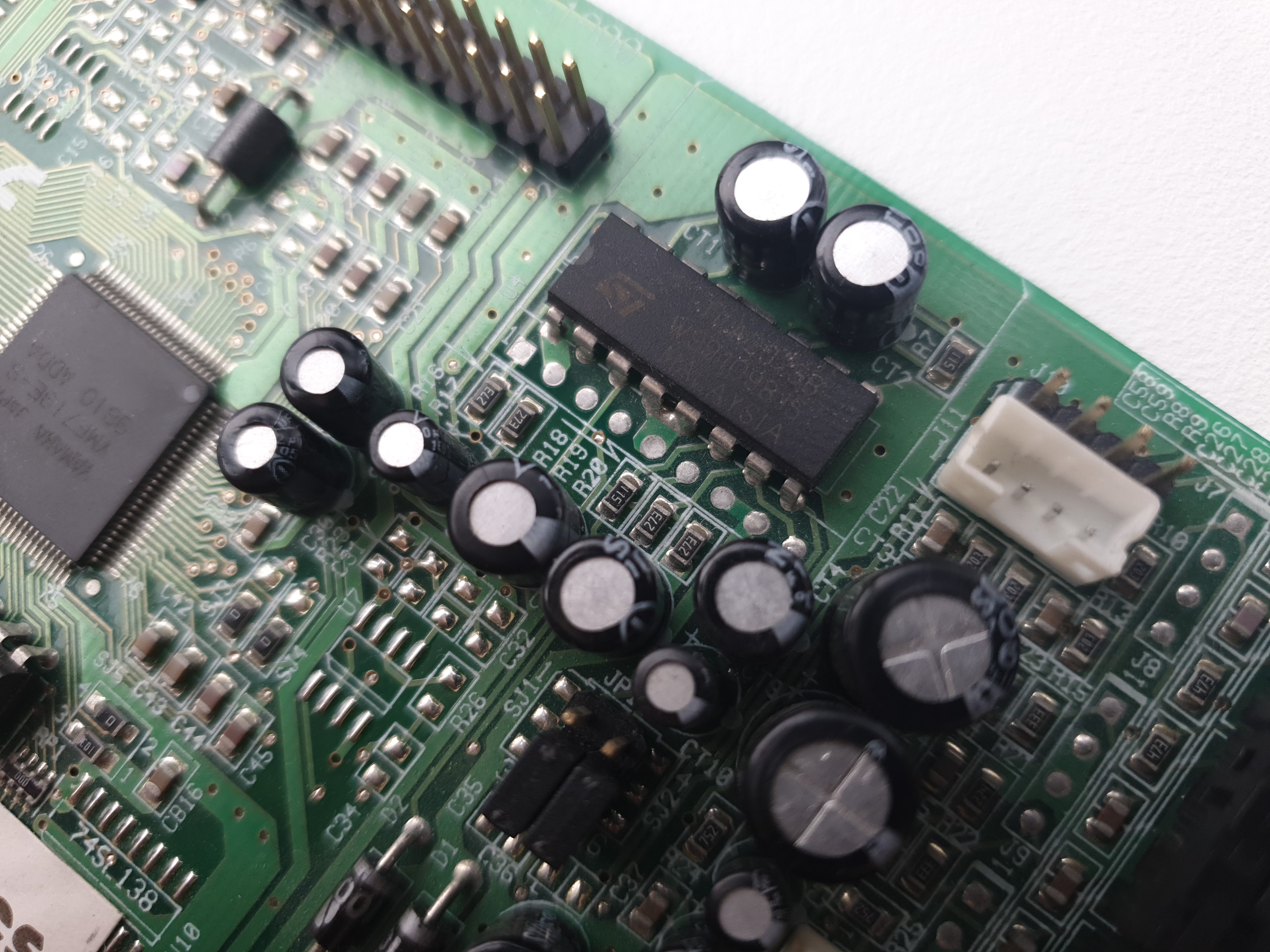 The onboard audio amplifier produces up to 2.4W per channel in stereo mode, or 4.7W mono.
This same TEA2025B IC from ST Microelectronics can be found on many ISA sound cards including the Aztech Sound Galaxy BX/NX/NX Pro 16/Basic 16/Pro 16, Creative Music System (CMS), Sound Blaster 1.0/1.5/2.0, Sound Blaster Pro, Sound Blaster 16, AWE32, and various OPTi-based cards with 82C925/82C928/82C930/82C931 chipsets, to name but a few.
Wavetable Header
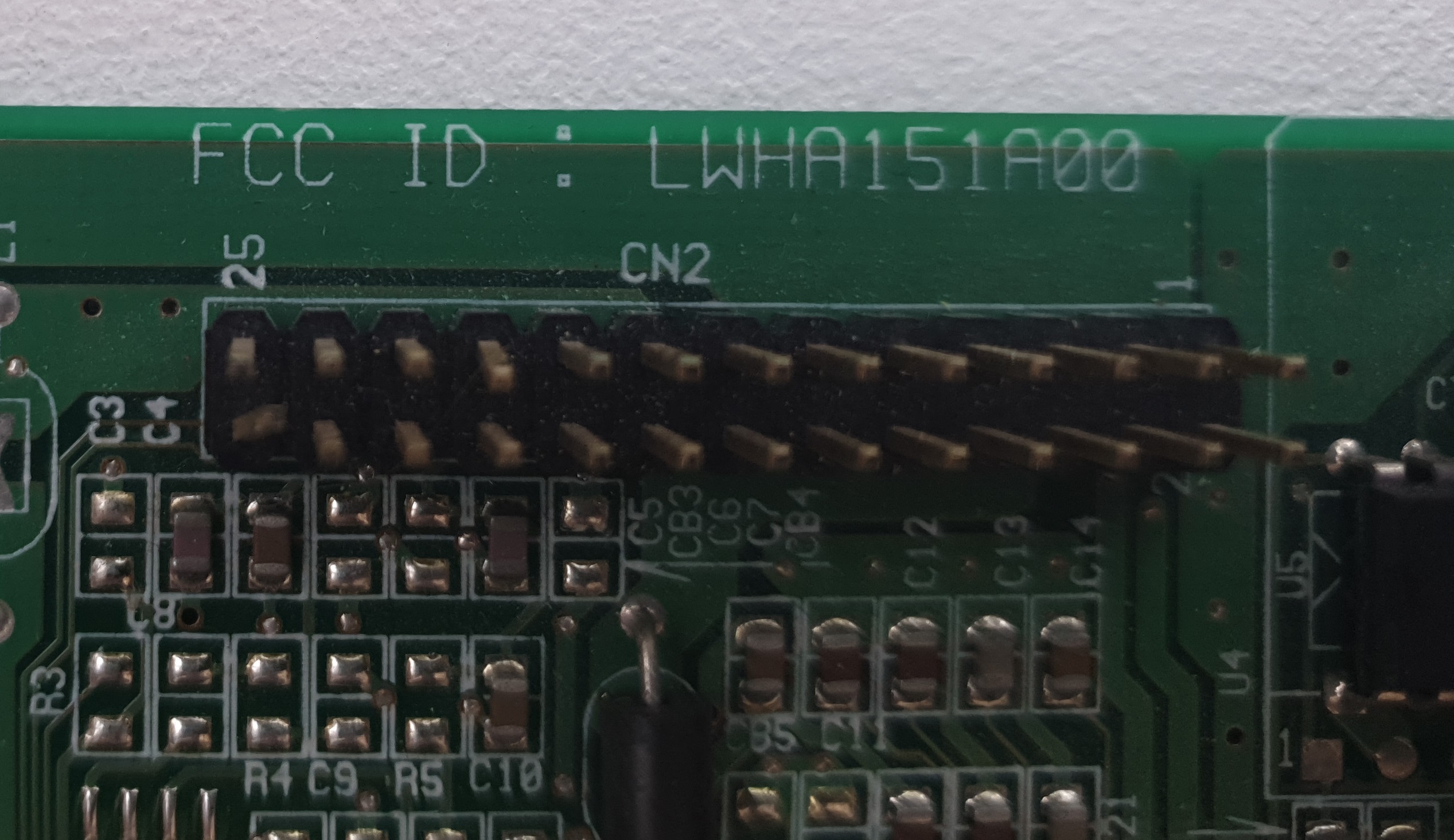 The 24-pin wavetable header is General MIDI-compatible and the Yamaha's chipset provides MPU-401 UART capability to this port. This opens up the card to be used with over 20 wavetable daughterboards that are compatible with Creative Labs' Wave Blaster.
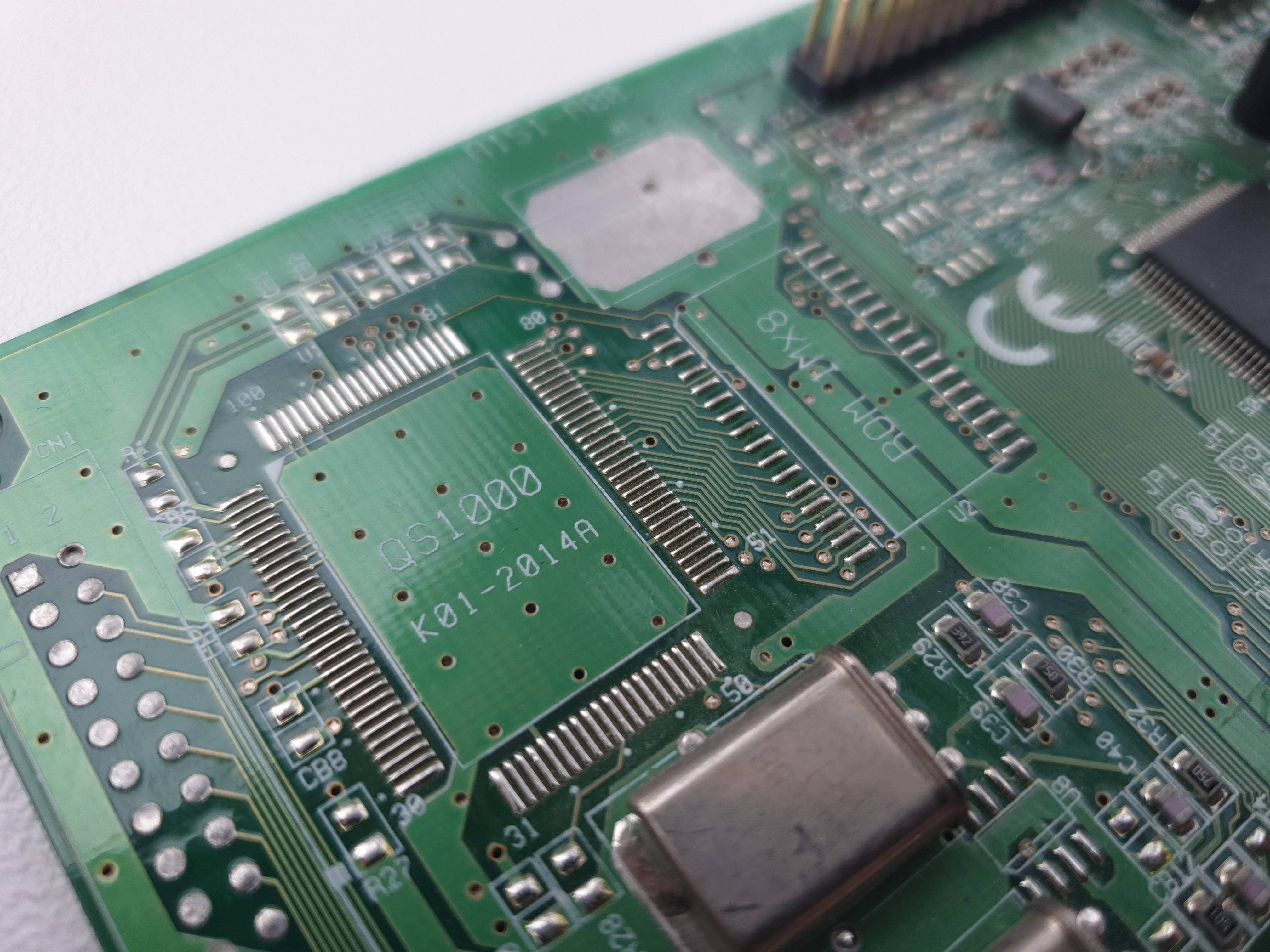
Pads for QS1000
The card also has provision for the AdMOS QDSP QS1000 wavetable audio processor and an appropriate 1 MB ROM chip to hold the instrument samples. It is rare to see an Audician 32 Plus card that has these chips soldered-in, but they do exist - I have a picture of such a card on my Yamaha page.
 The QS1000 was released in 1996 and was a cheap wavetable audio processor with options for 512 KB, 1 MB or 2 MB ROM capacities. I put it in the worst-quality category on my Wavetable Audio page along with 14 others, out of 43 chips in total, so it's probably better to just use the wavetable header and fit a better-quality daugherboard to this card if you want decent General MIDI capability.
Based on the missing components on my card, getting onboard wavetable audio onto this card would require:
- AdMOS QS1000 chip (100-pin PQFP)
- AdMOS QS1001A 1 MB ROM chip (32-pin PQFP)
- An extra crystal oscillator (24 MHz) on the large ground pad
- 8 capacitors
- 4 resistors
The Crystal Oscillators
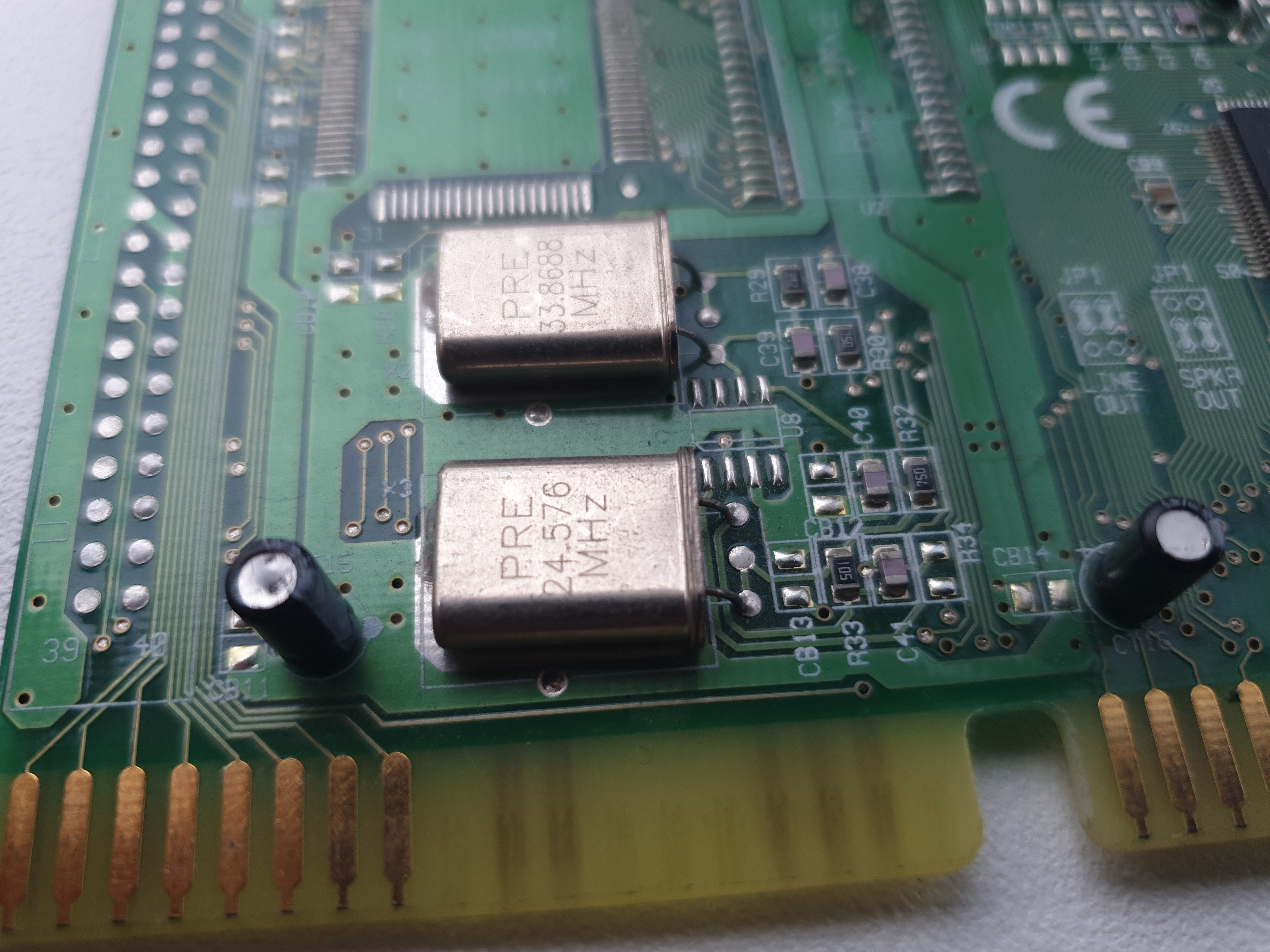 My card has two crystal oscillators on board. The upper one is 33.8688 MHz and the lower one is 24.576 MHz.
The 24.576 MHz one is used for the 48 kHz audio mode (512 x 48 kHz), and the 33.8688 MHz one allows integer division down to all the lower audio frequencies, comprising 44.1 kHz (768 x 44.1 kHz), 22.05 kHz, and 11.025 kHz.
This tells me that some of these YMF718 cards that do not have the lower crystal will not support the higher 48 kHz frequency.
Headers and Jumpers
As I mentioned, this card is ISA Plug & Play, so there are no jumpers to set the I/O address, IRQ or DMA channels.
The white header block at J10 is for CD audio-in from a CD-ROM drive. The four pins directly above the header block at J10 are probably also for CD audio-in, just for connectors that may not fit into the white block.
The second white header block at J13 is for microphone input if you want to connect a front panel connector to the card to get a mic-in jack working from the front of your PC. The missing jumper (again, solder pads only) at JP2 is most likely to select between a condenser microphone (pins 1-2) or a carbon microphone (pins 2-3).
.jpg) The main jumper block at JP1 is used to select the audio output as "Line-Out" or "Speaker-Out". Line-Out mode would mean the onboard amplifier circuitry is circumvented so the output would be unamplified while Speaker-Out is amplified. Why are there two jumpers? Probably for the 2 channels (left and right). The card is currently setup as Speaker-Out. For best signal-to-noise, it is usually preferable to use the unamplified "Line-Out" and connect the card to powered speakers or better still, a high-quality stereo amplifier, since a lot of noise is generated in a sound card's amplifier circuitry.
The main jumper block at JP1 is used to select the audio output as "Line-Out" or "Speaker-Out". Line-Out mode would mean the onboard amplifier circuitry is circumvented so the output would be unamplified while Speaker-Out is amplified. Why are there two jumpers? Probably for the 2 channels (left and right). The card is currently setup as Speaker-Out. For best signal-to-noise, it is usually preferable to use the unamplified "Line-Out" and connect the card to powered speakers or better still, a high-quality stereo amplifier, since a lot of noise is generated in a sound card's amplifier circuitry.
Being a pretty cheap card, there are numerous missing header pins (just solder pads) at J7, J8, and J9 (all 4 pins each). The tracks from these are connected to the Audio-Out, Line-In, and Mic-In jacks respectively, so just as with J13 I mentioned above, you could have pins on these to connect a front panel connector. Also most of these card lack the actual 40-pin IDE connector, which for most of us is a non-issue as our motherboards tend to have two IDE interfaces that support two drives each. For some, however, they are using an IDE controller card, and the two drives might be limited. Vogons member RJDog looked into modifying his Audician 32 Plus to add the missing IDE connector. He got it working, which you can read about here.
In Part 2, I will install the DOS drivers and test the audio capabilities of this unassuming little card!