XT Restoration Project - Part 2
In Part 1 I dug out all the parts from my original XT-compatible PC from 1990 and fixed the motherboard's keyboard error message and the monitor's dodgy cable. The computer is now booting successfully to a C: prompt with the use of an XT-CF Lite expansion card and an appropriately partitioned and FAT16-formatted Compact Flash card.
In Part 2 I shift my focus to looking at the other original components: the case, power supply, front panel and the floppy drives.
As I briefly mentioned in Part 1, the case of my PC resembles a modernised IBM 5160 case in terms of size and composition. Sure, the front design is different but the two piece case itself is just like an IBM - made of thick sheet metal (grey on the top and black powder-coated bottom and rear). It's looking a bit scrappy right now, so it would benefit from a respray and retrobrite (which I've never done before):
.jpg)
The front used to be the same colour as the rest
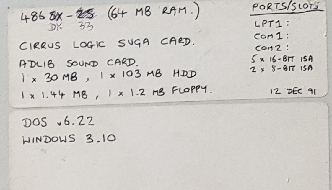
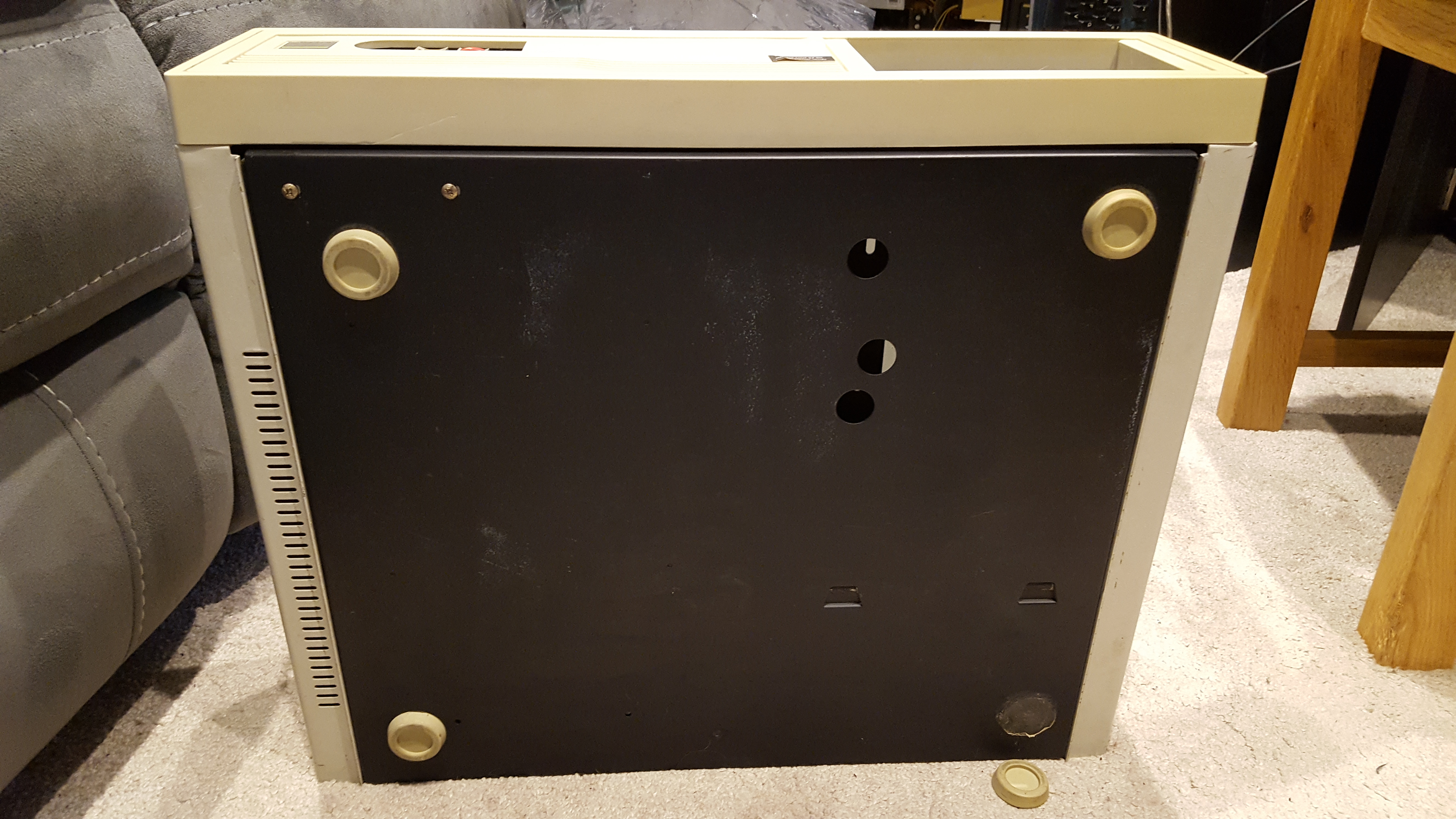
The left side shows a sticker with its specs from late 1991, and inside the case I've found the missing foot!
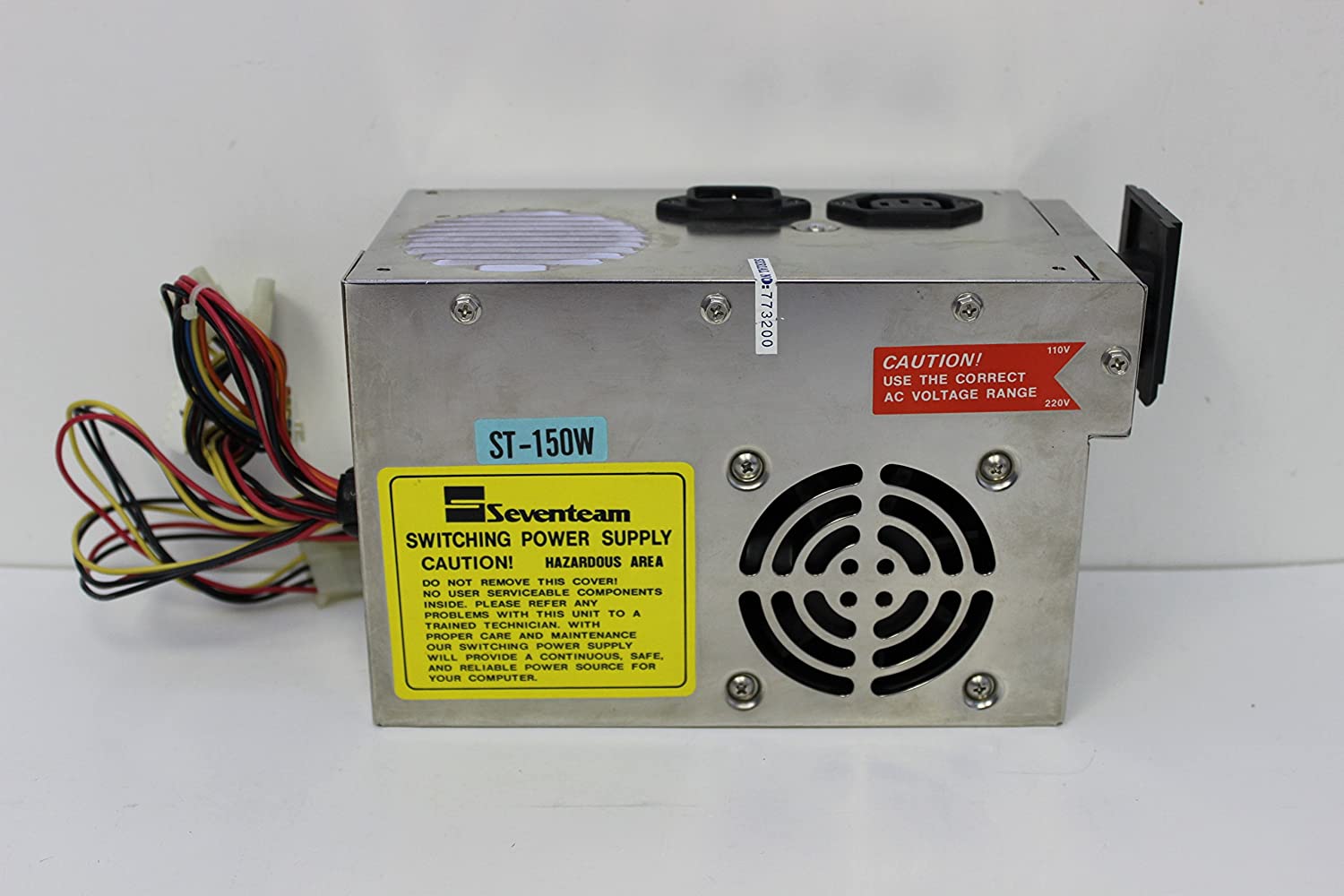
The power supply that came with the Morgan Base XT is a Seventeam ST-150W. This 150W is about on par with the IBM 5160's 153W if you had the larger 20 MB hard disk, though if you just had the 10 MB version you got a 130W PSU.
I really don't know if Seventeam are a premium brand or not - all I know is they are still around today - but aside from one repair back in 1991 (most likely after I upgraded the computer, so I probably overcooked it) this has run beautifully. The guy who repaired it was a friend of the family called Dennis Wildman - a very talented electronics engineer. Dennis had the forward thinking to disconnect the 220V/110V toggle switch while he was in there to avoid basic human stupidity in the future.
Problem No. 3 - DEAD POWER SUPPLY
Unfortunately the last time I brought this out to test I heard a bang on powering it up and the thing went dead. Let's take a look inside...
Here's the power supply board all cleaned up. You may notice I have started to disconnect the glass fuse (bottom-left corner) as it's blown. Unfortunately replacing the fuse has not brought it to life. I'm now thinking my best course of action is to replace the entire circuit board with a modern, more efficient one - brand new PSUs can be picked up pretty cheap these days and my AC electronics skills are rather rusty to be poking around in high-voltage circuits.
I have ordered a 300 watt CiT M-300U ATX power supply for £17.99 (brand new) from Scan.co.uk, and will use an ATX to AT adapter cable to change the ATX header into 'AT' P8 and P9 headers for the XT motherboard.
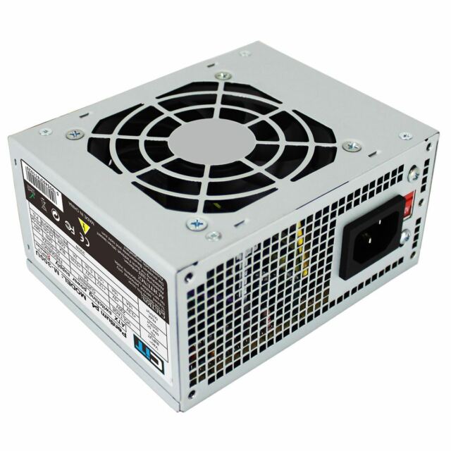
A brand new CIT M-300U 300W ATX power supply
You do need to be careful when choosing an ATX power supply to use with an AT motherboard (and ATX to AT adapter). Let me explain... An AT power supply feeds the motherboard with +5V, -5V, +12V and -12V lines. An ATX power supply does this too, plus a +3.3V line. Each line has a rating which is the maximum sustained current on that line. The table below shows the typical maximum current draw for each set of those lines, on various power supplies: two AT and two ATX.
| Voltage Line(s) | AT 200W PSU | AT 300W PSU | ATX 300W PSU | ATX 500W PSU |
|---|---|---|---|---|
| +5V | 20A | 15A | 8A | 3A |
| -5V | 0.5A | 0.3A | 0.8A | 0.3A |
| +12V | 8A | 12A | 9A | 34A |
| -12V | 0.5A | 0.5A | 0.5A | 0.8A |
You see, modern PCs rely more heavily on the +12V line(s) so many ATX PSUs have a very weak 'capacity' on their +5V lines. If you use an ATX power supply with a low max. current for the +5V line in a PC that ordinarily expects an AT power supply with a lot of power-hungry devices installed you could easily cause the ATX power supply to fail or cause damage to your computer. That 3A (in red) on the ATX power supply's +5V line is shared across all 5V lines from the PSU (the four that go into the AT adapter and through to the motherboard, and four more into the Molex connectors that power the drives). Those 3 amps can be used up pretty quickly, given that a typical 5.25" floppy drive will use about 0.5A on its +5V line during a seek operation, a hard disk 0.7A, a CD-ROM drive 0.3A, etc. So just those 3 drives alone are going to use up HALF the 'capacity' available on the above ATX 500W PSU, and don't forget the motherboard and all its expansion cards also use the +5V lines too. All these drives also use +12V but this is less of a concern as there's plenty of +12V line capacity with ATX power supplies.
Contrast this with the two PSUs on the left which have ample maximum current flow figures on the +5V line. The third PSU should suffice with 8A @ +5V and 9A @ +12V.
Anyway, back to the main event... The new CIT M-300U power supply can manage up to 16A on the +5V lines, comes with four Molex connectors (excellent), one 3.5" floppy drive power connector and one SATA connector which of course won't be used, so it's a very good fit for use in an old PC.
In part 3 I plan on transplanting the circuit board from the new M-300U PSU into the original Seventeam PSU casing in order to retain the old-skool big red power switch, cooling fan and possibly even solder in a mains passthrough to the monitor power socket (modern power supplies don't provide power for a monitor - I think it's a nice touch as you have a single plug for your whole computer into the wall, and the monitor can auto-power on when you switch the computer on!).
Onto the front panel, and this isn't in too bad a condition - just the Turbo switch and LED appear to be missing:
.jpg)
I love how they took the time to have their own logo manufactured - it's a proper metalised piece too, just like on an IBM!
Here's the front panel as it is mounted to the case front, and removed:
So there's a little bit of repair work to be done here. The front panel is missing its green Turbo switch and the Turbo LED isn't in it's housing. Apart from that it's not looking too shabby. If I'm being picky the keylock is a bit banged up but that's a minor point.
Looking through my old PC parts bin I couldn't find the green turbo button, but I did find some other goodies that I could possibly use for this project:
There's a front panel unit from a mini tower with some switches installed, 4 drive bay fascias of different shades, some motherboard standoffs and screws, a set of keylock keys, some stickers for the expansion slots, a bag of metal mounting brackets and screws and two expansion slot faceplates with ports on. The left has a game port and a serial port and the right has 2 serial ports.
First off, let's see if one of those front panel switches will work to replace my Turbo switch. Of course being a Turbo switch it needs to be a true 'push to make' switch, not a momentary switch like 'Reset'. There are two switches on this panel, one marked Reset SW and the other Power SW. I took my mulimeter to the Power SW one since Reset switches are always momentary. Unfortunately the power switch is momentary as well, which means this panel came from an ATX system where a single 'power on' signal is all it needs. Shame. The metal brackets I'm thinking I can use with the new PSU - I need to make sure the much smaller circuit board is safely elevated off the floor of the large Seventeam PSU casing.
Back to the front panel, now is a good time to write down the wiring colours...
| Power LED | Green / Black |
|---|---|
| Hard Disk LED | Red / Black |
| Turbo LED | Yellow / Black |
| Reset Switch | Red / White |
| Turbo Switch | Green / Brown |
| Keylock Switch | Yellow / White |
| Speaker | Blue / White |
All of these are pins on the XT's motherboard with the exception of the hard disk LED, which will be connected to the XT-CF Lite's LED pins in the top-left corner of the board.
Since I'm now waiting for a number of parcels to arrive, let's get the board into the case and wired up...
.jpg)
.jpg)
.jpg)
.jpg)
Clockwise from top-left: (1) empty case, (2) motherboard standoffs in place, (3) board in, (4) front panel wiring installed.
Now to get some cards installed. Currently I'm trying to get this back to 'stock', or as close as possible.
You've already seen my Hercules card(s) in part 1 - now onto the floppy disk controller. I actually don't have an XT-class floppy disk controller that would have been used back in 1990 - one that only supports drives up to 720 KB. The only card I have is really one of my planned "upgrades":
It's a multi-I/O card much like the original that came with this computer, though this one has its own ROM BIOS in order to support high-density floppy drives in an 8-bit PC - what an upgrade that would have been in 1990! The card also features a realtime clock, 2 serial ports, parallel port and game port. That's a lot of bang for the buck in a single card!
And into the case it all goes...
next to one of those expansion slot faceplates - the one with the two serial ports - one 9-pin and one 25-pin, since the card has its parallel port on the card backplate.
I installed my original 360 KB 5.25" floppy drive and this works (at least, the light goes on when I request the A: drive - getting a disk to read is another story - more on that later!). However, the 3.5" 720 KB drive that I got about 7 months later (Christmas 1990) doesn't want to work with this controller. I moved it to my main retro PC and it worked just fine, including reading disks, so there's something odd going on with this floppy disk controller and the drive.
Anyway, here's a pic of the drives both installed as it was after Christmas 1990 (please forgive the mess in my den - I have four PCs in here right now, some in bits, monitors and cables everywhere):
Somehow, my 3.5" drive looks wrong - it came with this metal 5.25" drive bay housing that you see in the pics, but I'm certain it used to be flush with the front rather than protruding - it just seemed to want to sit 'outside' like you see here. I do love this 3.5" 720 KB drive though, partly because it's so unique with it's eject button underneath - I had not seen that anywhere before apart from the Commodore 1541, and not since* so get in touch if you've seen this design anywhere else (btw, this drive is a YE-Data YD-645B. You will find nothing on the web about this drive - it's not even in the DOS Days list of floppy drives, but it has a real retro vibe - it had that even when I got it brand new - when I first unboxed it I was aware of what a typical 3.5" floppy drive looked like with the little eject button to the right side, but this little guy soon won me over with its charm!
*Actually, I saw this advert in PC Magazine, 24th November 1987, which has a similar eject button on a 5.25" drive! According to the ad, these are low-density "direct drive" (not belt driven) ones and are a famous brand.
**UPDATE! EEPROM Programmer and 5 EPROM Chips have arrived**
Pretty good delivery time, about 4 days. I unboxed the Programmer and was a little underwhelmed - it didn't come in the blue box as pictured before - it was just in a small cardboard box for shipping, and then bubblewrapped in there. Hmm, makes me wonder if it's a brand new item or not.
Anyway, rather than trying to dig out a CD-ROM drive for the mini-CD-ROM included in the box, I downloaded the EPROM programming software from here:
https://icmasteronline.com/product/xp8710-universal-usb-icsp-programmer/
The downloaded file was called SetupXP8710.rar, and contained a single file called SetupXP871.exe. About 4 MB in size.
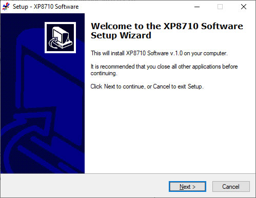
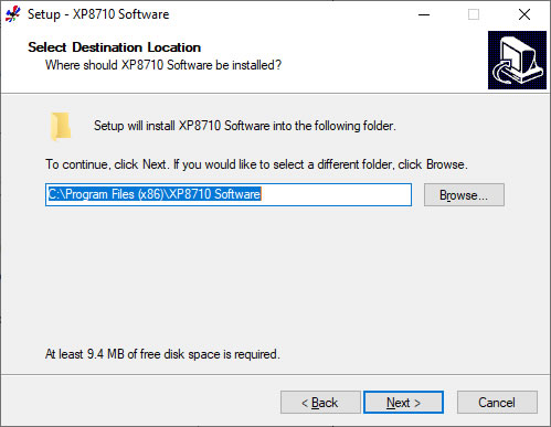
Once the installation was nearing completion, this ambiguous prompt appeared:
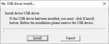
To which I'm thinking 'this USB driver has not been installed, but I do have a USB driver already installed. So should I hit Install or Cancel?
I decided to hit 'Install':
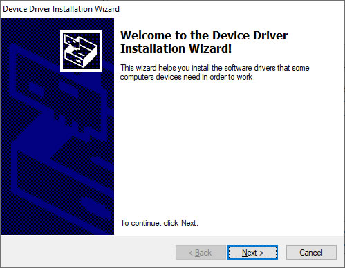
It then asked me if I was sure I wanted to install the driver, along with a box that said 'Always trust software from Shengzen...' which I unticked and proceeded:
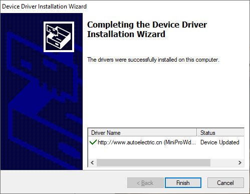
The full Driver Name in the screenshot above read: (MiniProWdf) WDFMiniPro (06/22/2012 1.0.0.0). An oldie but a goodie I hope! Incidentally, the TL866 programmer I referred to before is called the MiniPro, so this XP8710 product is either the same under the hood or it just uses the same software.
Anyway, I fired up the "XP8710 Software" app from my desktop:
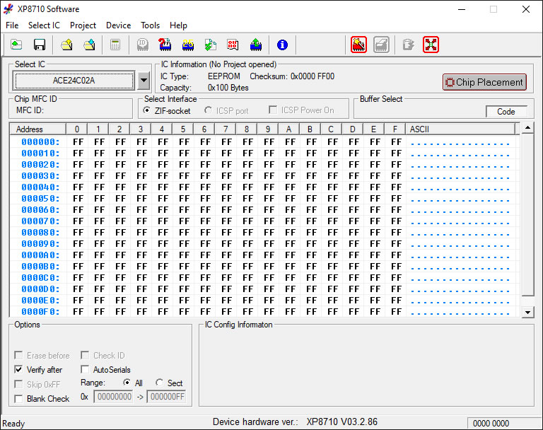
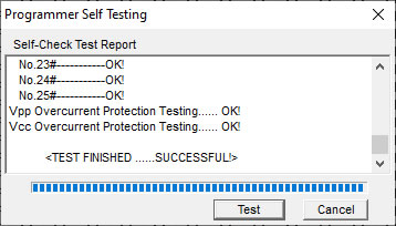
I started with a Self-Test of the Programmer:
To tell the software what chip I had inserted, I went to "Select IC" in the top-left corner and tried to locate the one I have:
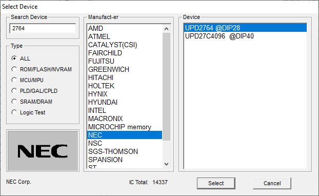
So unfortunately, there is no Mitsubishi 2764 in the supported ICs list. A quick Google told me the TL866 range don't have this either. The one I highlighted above is a compatible chip, however. Both have identical pinouts and operate on 5V, and both enter programming mode with +21V on pin VPP.
After choosing the IC, it gives some parameters that are selectable at the bottom:
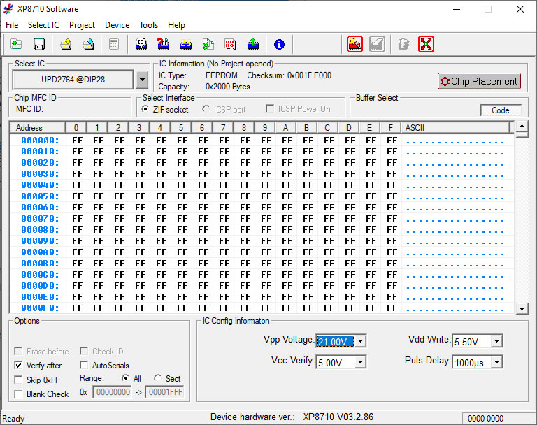
I then chose the Device menu and picked the 'Read Chip' option. It popped up with a graphic reminder of the chip's orientation, and I clicked 'Read'. As expected since the EEPROM's quartz window is exposed to UV light, the chip is empty (0xFF in all bytes). So now is the time to cover up the window.
I then chose 'Open File' and located my dumped ZETA P-10 .bin file (the 8 KB one):
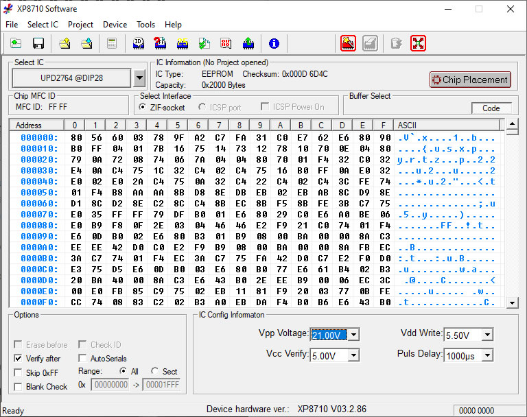
followed by Device menu -> Program Chip. I quickly got this error after starting the burn:
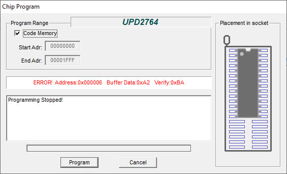
After playing around with a few of the settings, I have come to the conclusion that the programmer or the EEPROM itself is very susceptible to minor changes in voltage . I changed the USB port I was using and decreased the Vdd Write setting to 5.0V.
If all goes well you get something like this:
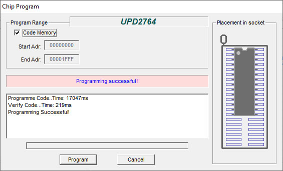
It's always a good idea to run the Verify operation just to be sure the chip has the same code on it as what's in the buffer (the .bin file you loaded):
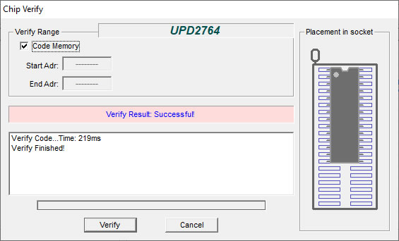
So there we have it - I have duplicated the P-10 ROM BIOS successfully in case my original dies.
Putting the monitor on top and a keyboard in place for the [almost] full effect...
Ah yes, that's how I remember it... undersized monitor, or oversized system unit - whichever. I learned to program in Pascal and C on this baby.
**UPDATE 25th Nov 2020: It's now been nearly 2 weeks since my order went to Scan Computers, so I'm really not too happy with their service. The primary item in this order is the CIT power supply, so I've had to delay work on this project until that arrives. Keep checking in for Part 3, which I hope to get completed in the next week**
**UPDATE 29th Nov 2020: OK, the new power supply is not coming - Scan don't know when they will next have it in stock, so I cancelled the order. I've found another modern ATX supply in my collection which should do the trick instead:
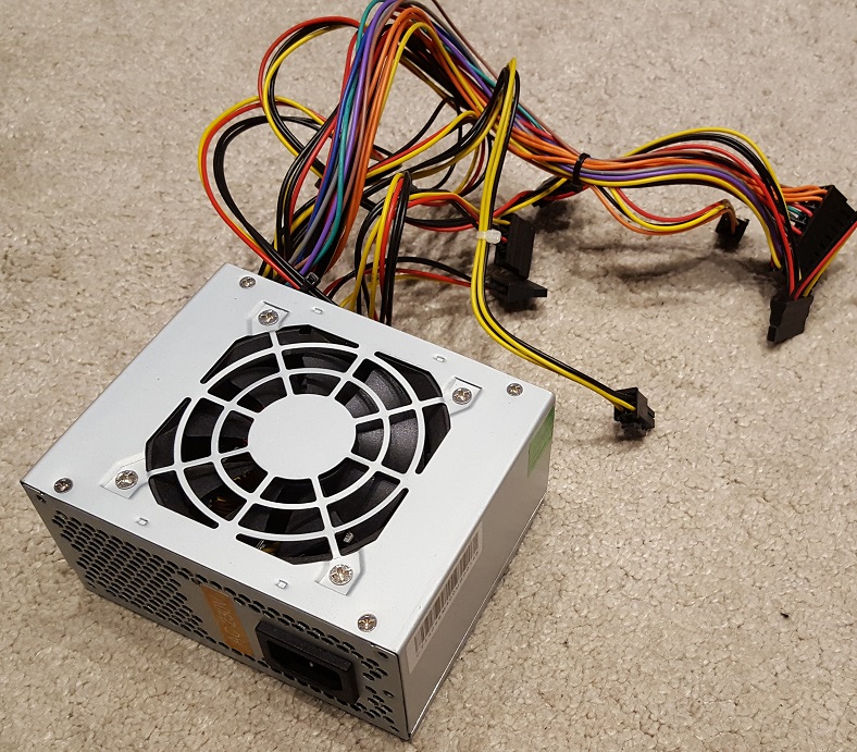
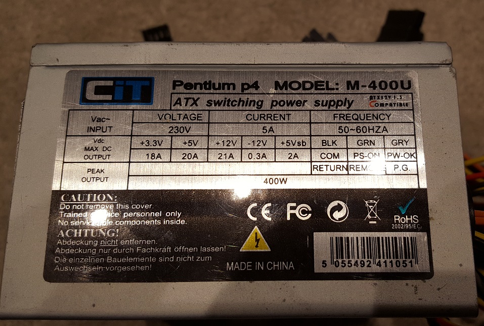
Also from CIT, though this one's about 10 years old - model M-400U. Most importantly, it handles up to 20A on the +5V line and 21A on the +12V line so good for an XT/AT.
It's been a good journey so far, but we're not quite there - I have grand plans to put into action in Part 3!
.jpg)
.jpg)
.jpg)
.jpg)
.jpg)
.jpg)
.jpg)
.jpg)
.jpg)
.jpg)
.jpg)
.jpg)
.jpg)
.jpg)