RGBtoHDMI Review - Part 1
25th February 2024
Introduction
About a year ago I created my own video converter using the GBS8200 and Necroware's digital to analogue adapter, and while this works just fine, it doesn't have many options to tweak the video image and it cannot store multiple profiles. In my intermittent scouring for new projects, I came across the RGBtoHDMI project - the functionality lacking in the previous video converter/scaler project are handled with the RGBtoHDMI, so I thought I'd buy one, get it set up, and review its capabilities for my purposes - specifically, to convert and scale MDA, Hercules, CGA and EGA video for use with a modern display.
The RGBtoHDMI project was originally created by Hoglet in 2018 for the Acorn BBC Micro 8-bit computer to convert and scale its analogue video output to display on a DVI or HDMI monitor. Later on, IanB joined the project and extended its use to a broader range of retro computers including IBM PCs and compatibles that run MDA, CGA or EGA graphics.
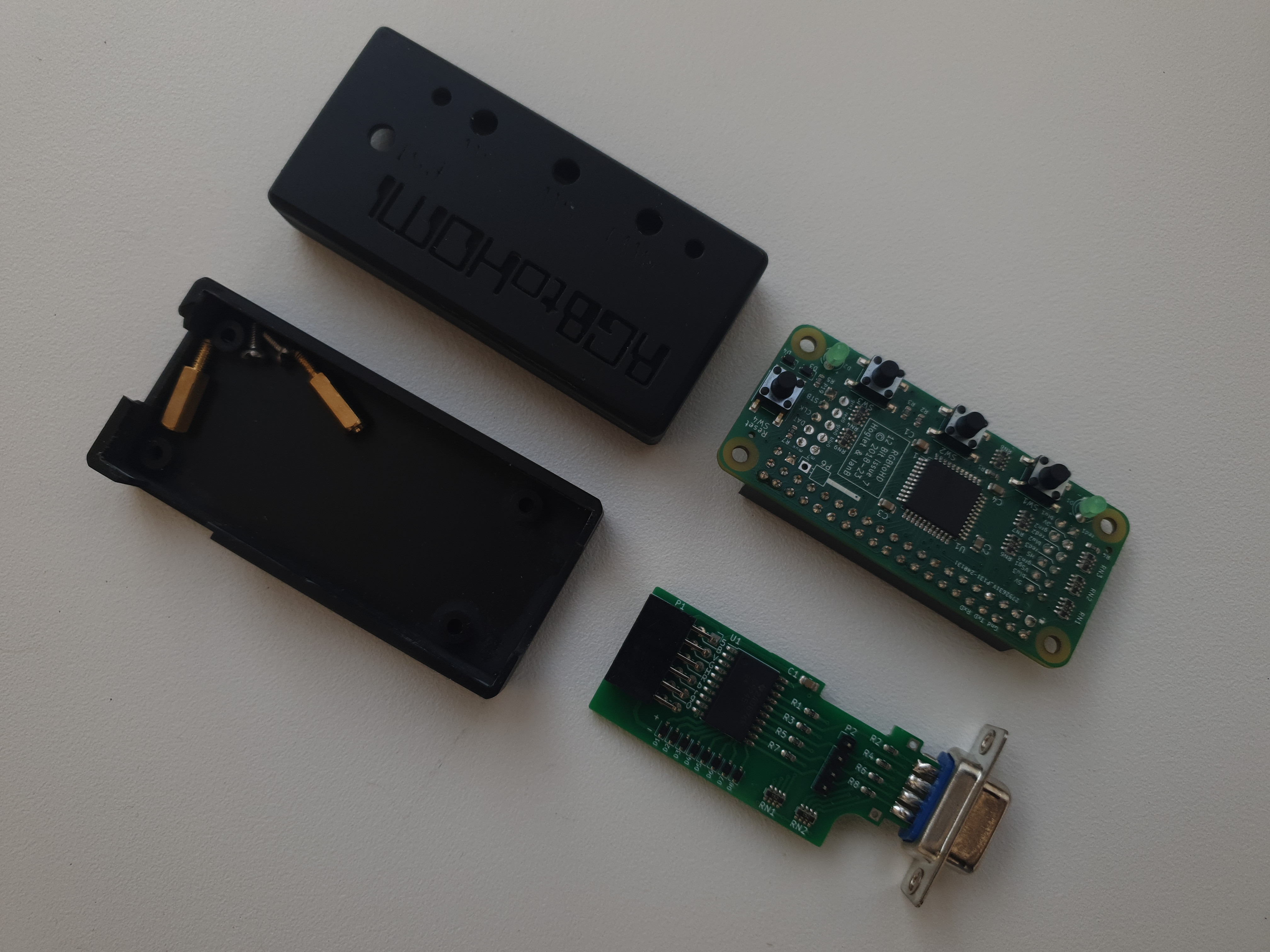
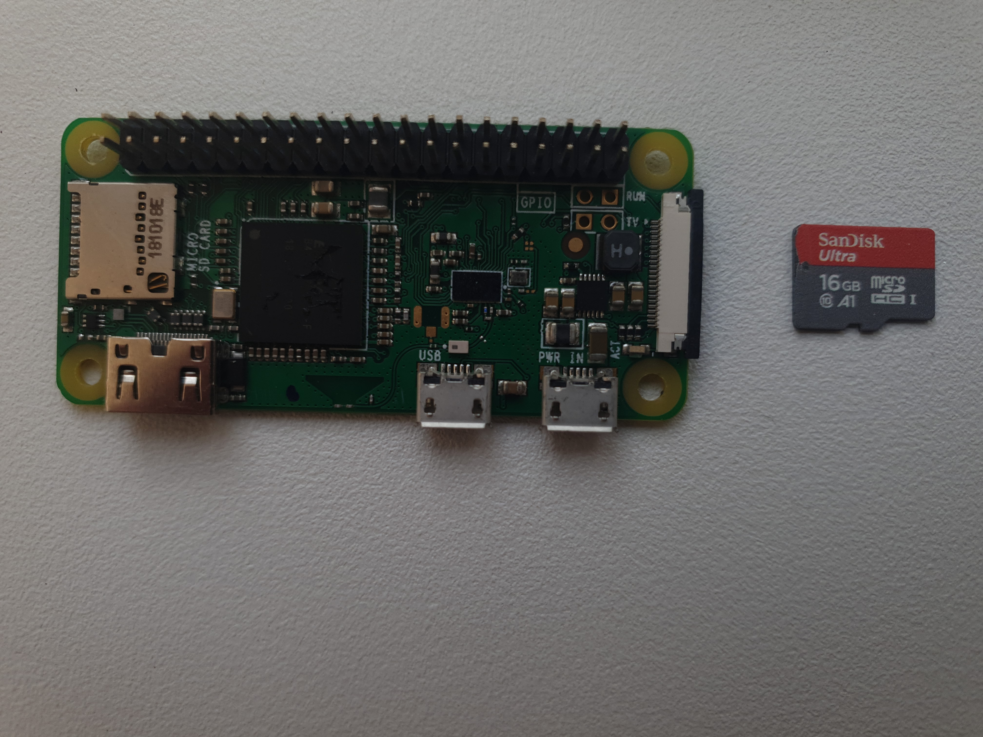
The 12-bit RGBtoHDMI, plastic case, and optional TTL buffer for IBM PC
Some key features of the RGBtoHDMI are:
- Extremely fast startup - because the RGBtoHDMI software communicates directly with the Pi's ARM processor and graphics subsystem, there is no waiting around for an operating system to start up.
- Almost zero lag - a common issue with many cheaper scalers/converters is a lag between receiving the input video signal and the converted/upscaled output video signal. Any noticeable lag can really detract from the usability of such a device.
- Profiles - this allows all settings to be saved and recalled quickly for different requirements - great if you plan to use the RGBtoHDMI on a number of different systems, or in my case, a lot of different MDA, Hercules, CGA and EGA cards. Sub-profiles also exist to keep the menu system clean.
- Integer scaling - good for pixel-perfect reproduction of the video image without the fuzziness you get from interpolation methods used by other scalers. Interpolation is still an option in the menu if you want to use it.
- Up to 1080p output at 50 or 60 Hz (4K is now also supported, though a Pi 4 is needed for these higher frequencies - a Pi Zero will only be able to run in this resolution at 25/30 Hz).
- HSYNC/VSYNC - All modes for horizontal and vertical sync are supported, including composite and inverse composite sync.
- Colour palette options.
- Output monochrome as either white, green or amber.
- Scanlines - for that authentic retro look.
- HDMI/DVI Monitor Autodetect - Automatically detects whether the connected monitor is using DVI or HDMI protocol.
The project's GitHub page provides information on where you can buy assembled boards - I bought mine from Ebay seller retro_tinkering for about £55, which included the optional TTL buffer and a 3D-printed case. I had a spare Raspberry Pi Zero v1.1 lying around, and used that for this project.
The Hardware
The main hardware for the project is a Raspberry Pi "Hat" that interfaces directly with a Raspberry Pi. You can buy the RGBtoHDMI hat with a variety of input video interfaces to support Atari ST, Amiga, ZX Spectrum, Amstrad CPC, Acorn BBC, and of course, IBM PC. At its core, the hat has a Xilinx XC9572XL CPLD (Complex Programmable Logic Device) that is programmed with custom gate logic that replaces what would otherwise require many separate ICs.
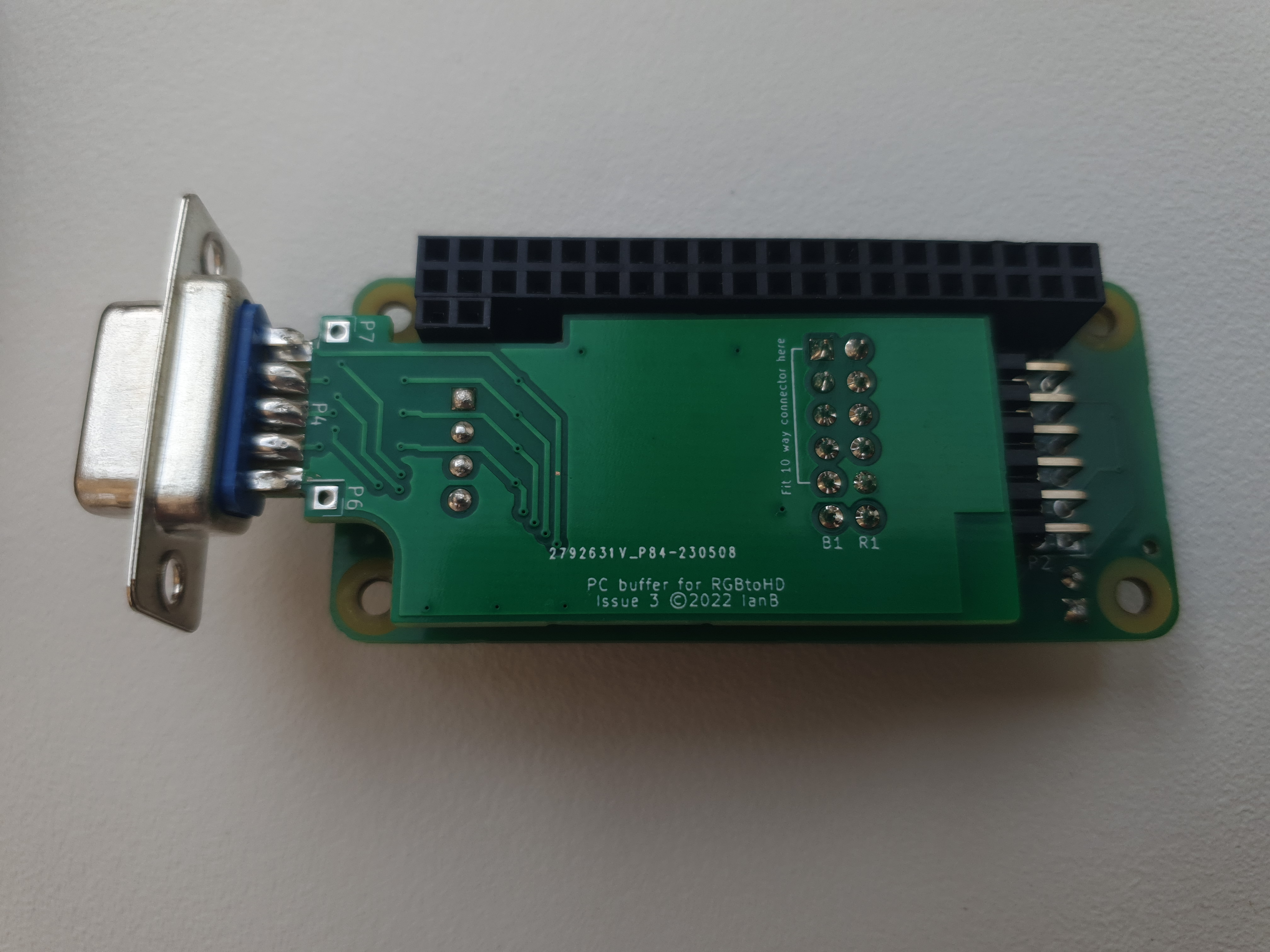
An optional add-on is a TTL buffer board. This buffers the input signals coming in, protects the CPLD from damage, and is an easy way to physically get the input video port(s) to the outside of the recommended plastic case for the RGBtoHDMI.
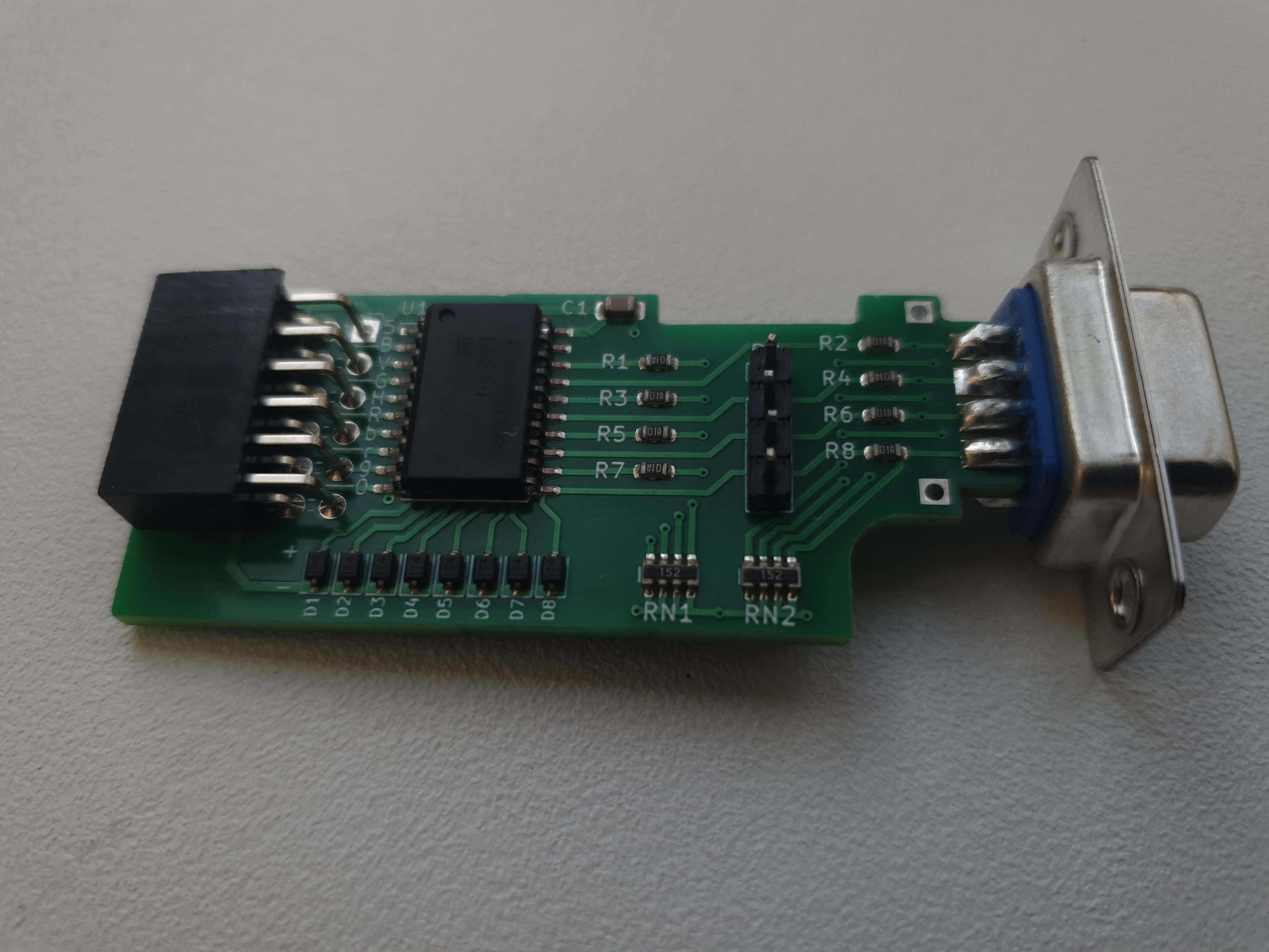
The optional TTL buffer board for the 12-bit IBM PC version of RGBtoHDMI
The LED to the left of SW1 indicates if Genlock is on - this means the Pi's video output is locked to the source video. According to the Wiki, this is the normal mode of operation and is used to keep the video in sync and prevent tearing or glitching of the video signal. It also means the lag (delay between input and output) can be kept to around 4 milliseconds because once genlocked, the phase relationship is arranged so that the Pi reads the video out of the frame buffer almost immediately after it has been written by the capture code. If the LED is off, the Pi's video output runs independently of the source video. When it's flashing, Genlock is in progress.
The Software
Custom software runs on the Raspberry Pi to drive the hat. This is extremely quick to boot up, providing a converted image on-screen within about 5 seconds of powering it on. There is no need to do anything complex to get the device up and running once you have the software on your Pi - all configuration can be done using the buttons on top of the RGBtoHDMI to call up the on-screen display (OSD) and navigate through the options.
Getting it Up and Running
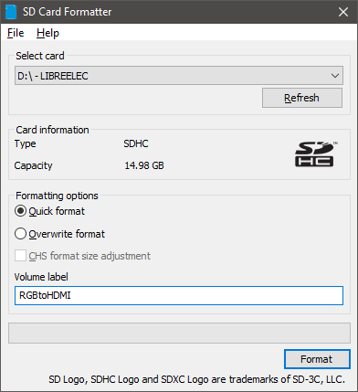 Step 1: Format a micro-SD card (2 GB minimum capacity) in your PC with an empty FAT32 file system.
I had a spare 16 GB one from SanDisk lying around and formatted it using the excellent SD Card Formatter utility by Tuxera. I've been using this utility for years, and it's a great way to restore a multi-partitioned SD card back to its full capacity and create a single partition.
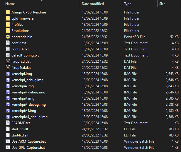 Step 2 is to download the latest stable release of RGBtoHDMI and unzip it into the root directory of the newly-formatted SD card. At the time of writing this article, we're up to the 20240213_e630d36f Release. When unzipped it's about 98 MB in size.
A typical release's directory structure is shown in the image to the left.
 Step 3: Put the micro-SD card into the Pi Zero. The socket is not a spring-loaded type you get on some devices. If you are installing the RGBtoHDMI into the recommended plastic case, you might struggle to get it in there if you put the Micro-SD card in at this stage - the case has an opening for you to do this later. With a bit of jiggling, I was still able to get it to fit into the case with the SD card already installed.
 Step 4: If you have the optional buffer board, install that now. Mine came already connected to the RGBtoHDMI, but for the purpose of seeing it all and taking some pics, I had disconnected it. Because there are two connections to be made, it works the best by first lining up that large block of pins, angle the buffer board up at the DSUB end and slide it onto the RGBtoHDMI connector block. Then the four pins closer to the DSUB will be sitting above an 8-pin connector block - the ones they need to go into are the four closest to the DSUB.
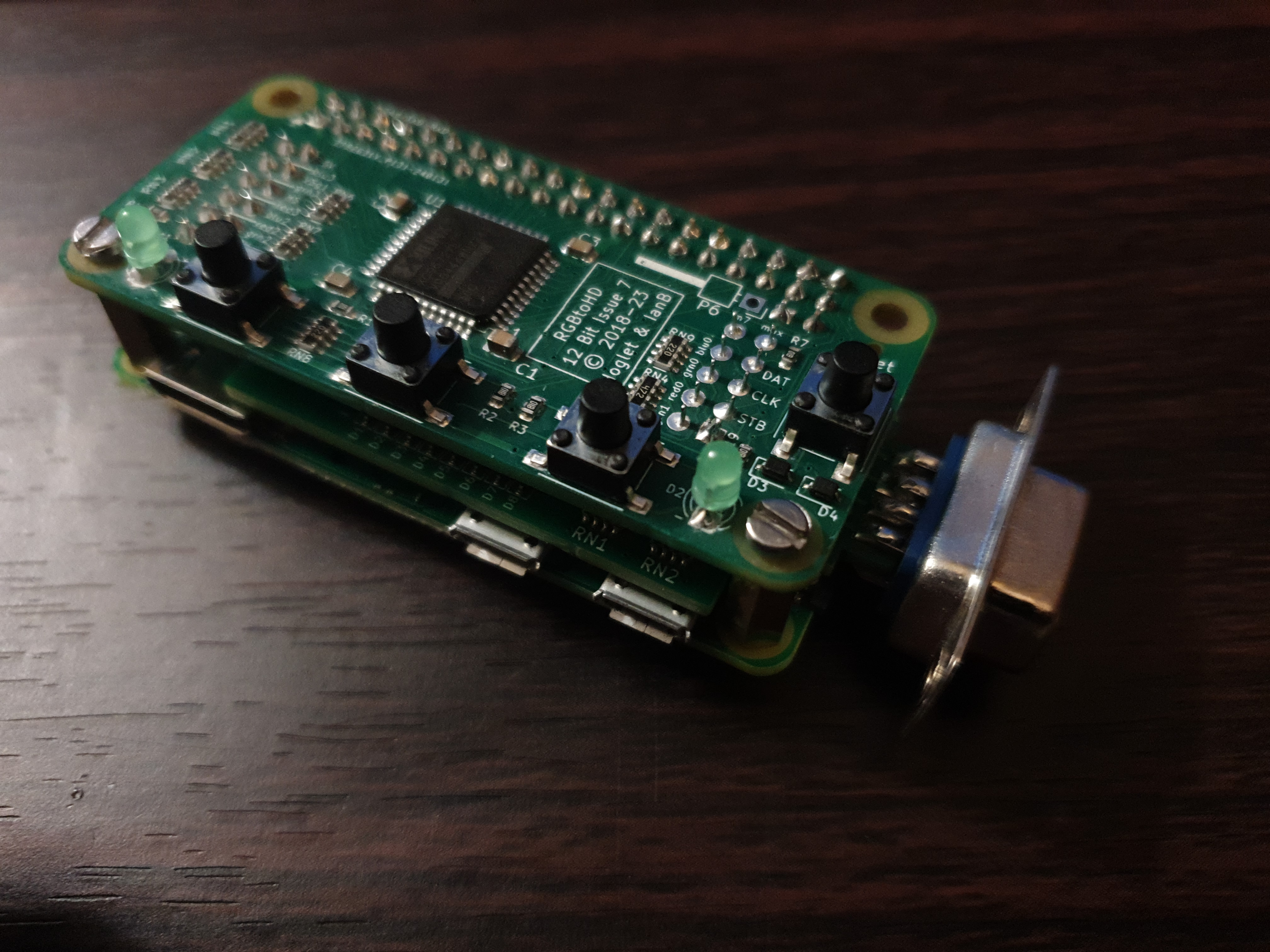 Step 5: Align the RGBtoHDMI (with optional buffer board attached) above the Pi Zero so that the Pi Zero's large GPIO pin block lines up with the pins on the underside of the RGBtoHDMI, and press down until all the pins are fully in. You should now have a compact sandwich like you see in the image to the right.
One thing to note here is that I had previously put a tiny heatsink on top of the ARM chip on my Pi Zero, but when I put the hat on top it wouldn't fit, snagging on the top of the heatsink. You can get very low-profile heatinks that might work, but mine at just 5mm tall was too high.
Step 6: Now for the cabling... attach the Pi to your display via a Mini-HDMI to HDMI cable, and the 9-pin DSUB video cable from your retro PC's video card to the RGBtoHDMI.
Step 6: Attach the Pi's power supply (note: on the Pi Zero this is the rightmost micro-USB port shown in the image above).
That's all there is to it !
On-Screen Display
Without any source connected, you can still access the OSD by pressing SW1 (the leftmost button) on the top of the RGBtoHDMI, and then use SW2 and SW3 to move around the menus, with SW1 selecting an option. Here are some screenshots of the OSD:
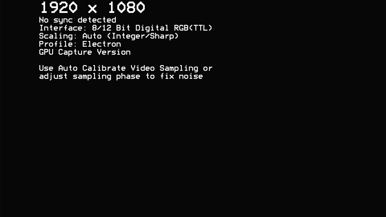
Out of the box, my RGBtoHDMI was configured to use the Acorn Electron
profile (or maybe just because that's the first one in the list).
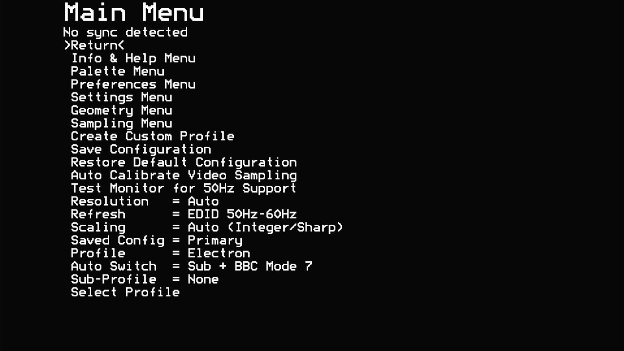
Pressing the button again brings up the Main Menu.
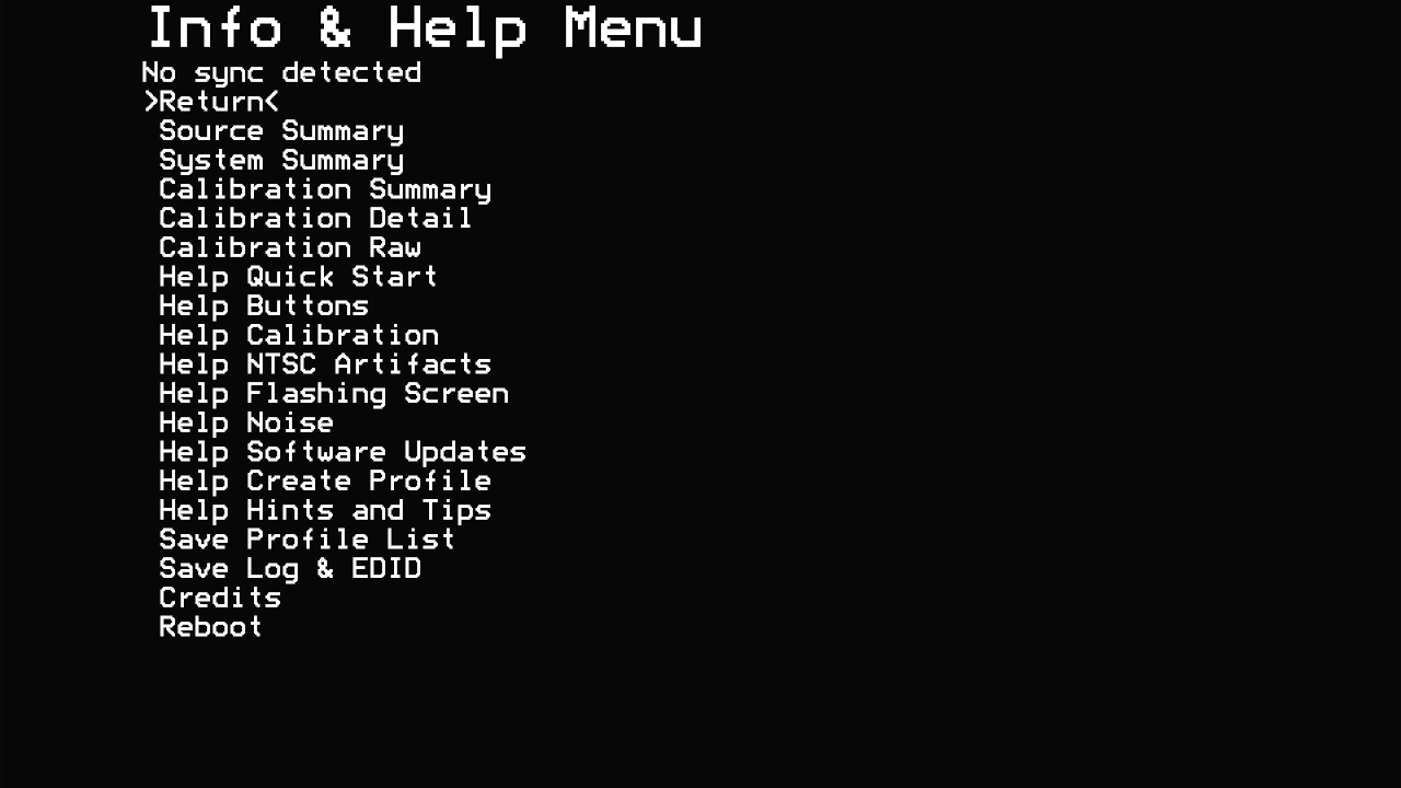
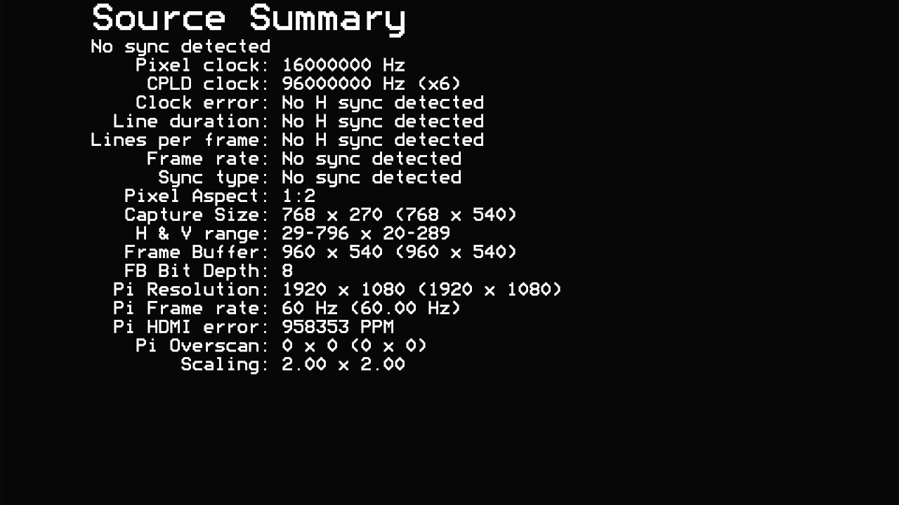
The Info & Help Menu, and then Source Summary inside that
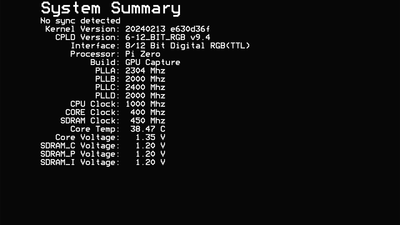
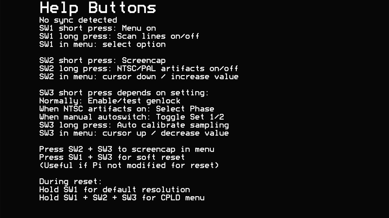
System Summary and the Help Quick Start option
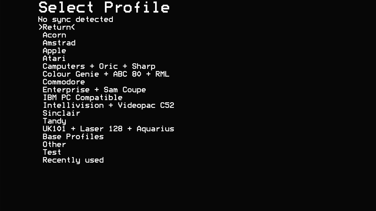
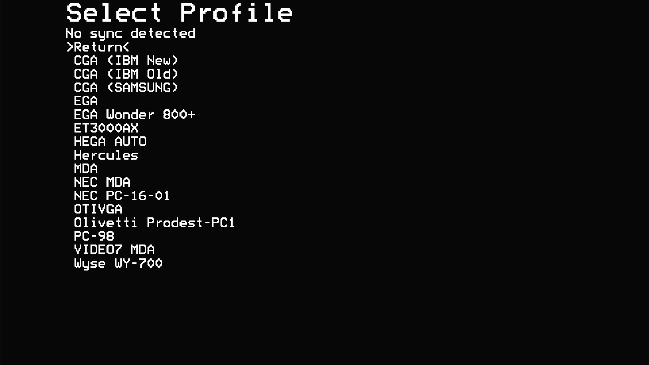
Going back up to the Main Menu and choosing Profile, and then the sub-menu after choosing IBM PC Compatible
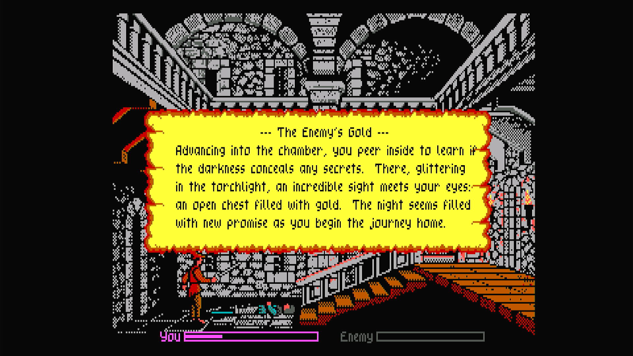
First Tests - EGA
To take videos and screenshots, all my tests took the HDMI output from the RGBtoHDMI and were fed into my USB HDMI capture dongle and from there into OBS v29.1.3. The output was kept at the standard 1920 x 1080 and then the files were scaled down to 320 x 200. Hopefully there was no loss in accuracy with this last step.
I still have the Octek EVGA-16 close by, so for my first test run I'll use that. I set the RGBtoHDMI to use the "EGA" profile, and started the PC...
All good, now to see what the EGA output looks like in a bunch of games. I'm not good at configuring the capture software, OBS, to a specific screen size without it doing some software-scaling on the image (which I don't want), so kept it at the default to be sure you see an unadulterated image of the output. Click on any image for the original non-resized version:
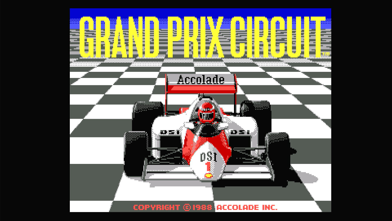

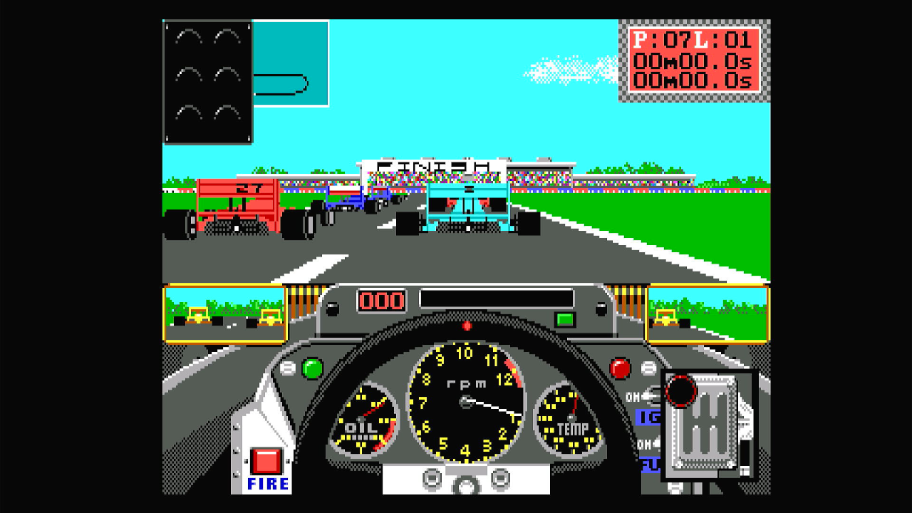
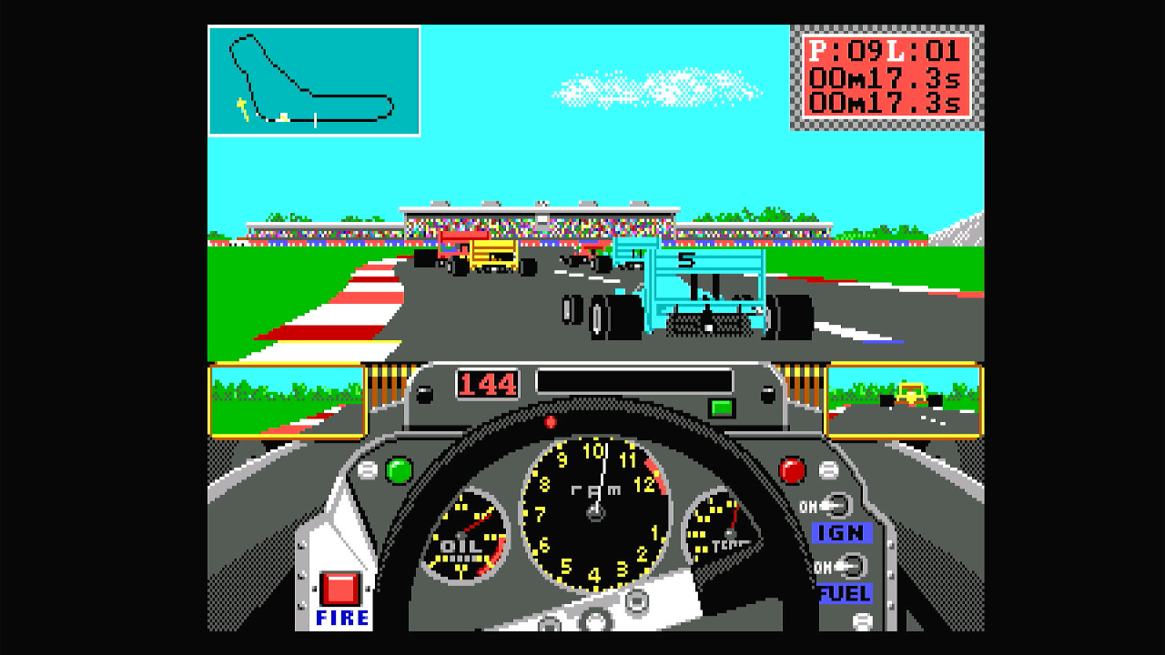
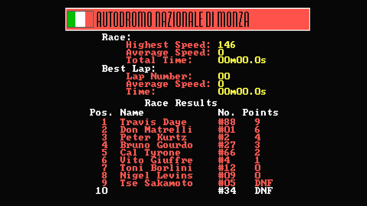
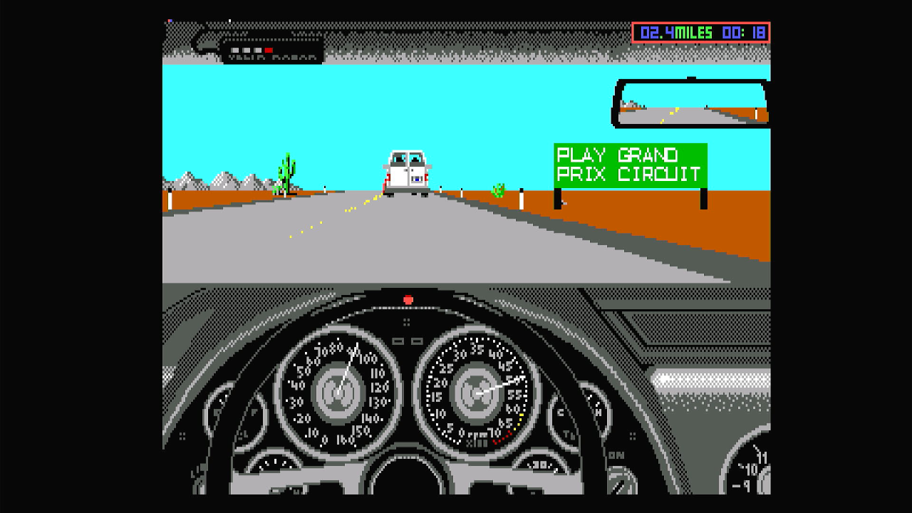
Grand Prix Circuit ran beautifully, with great colour accuracy and pixel-perfect scaling. And, most importantly on games like this, no lag!
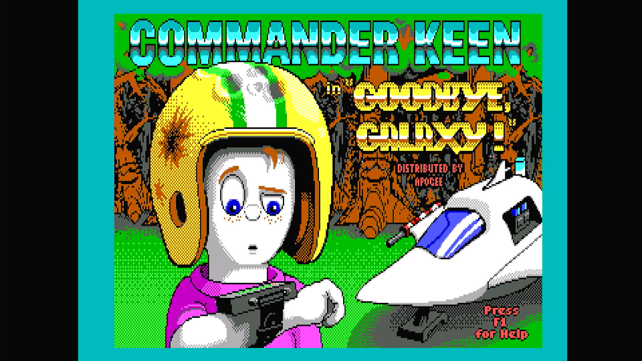

Commander Keen 4 incurred the commonly-known scrolling issue once you're into a level - the game was known to push the boundaries of video cards back then so 100% compatibility is patchy with this game anyway. In terms of colour and scaling however, the RGBtoHDMI did a bang up job.

Ah, F-15 Strike Eagle II... a great EGA DOS game! No lag and the colours really look great here.

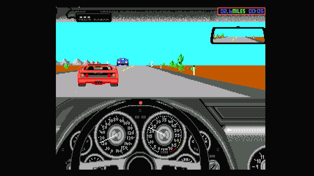
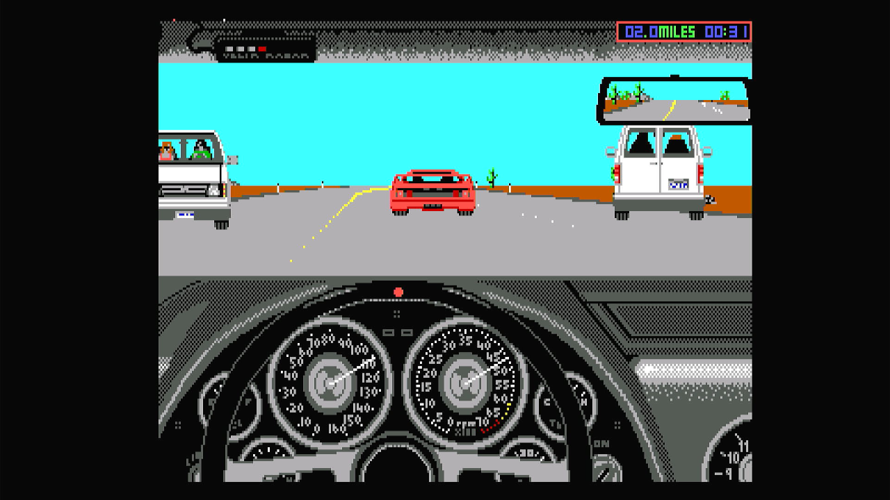
Test Drive II: The Duel also ran and looked great.
Their Finest Hour: Battle of Britain ran well but the in-cockpit view had these strange horizontal bars - it could be the Octek card's fault, but I don't recall seeing these before.

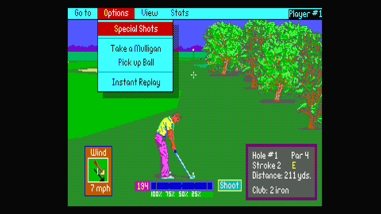
PGA Tour Golf is a very underrated golf game that looks amazing in EGA graphics mode. No issues were seen during my very brief play.
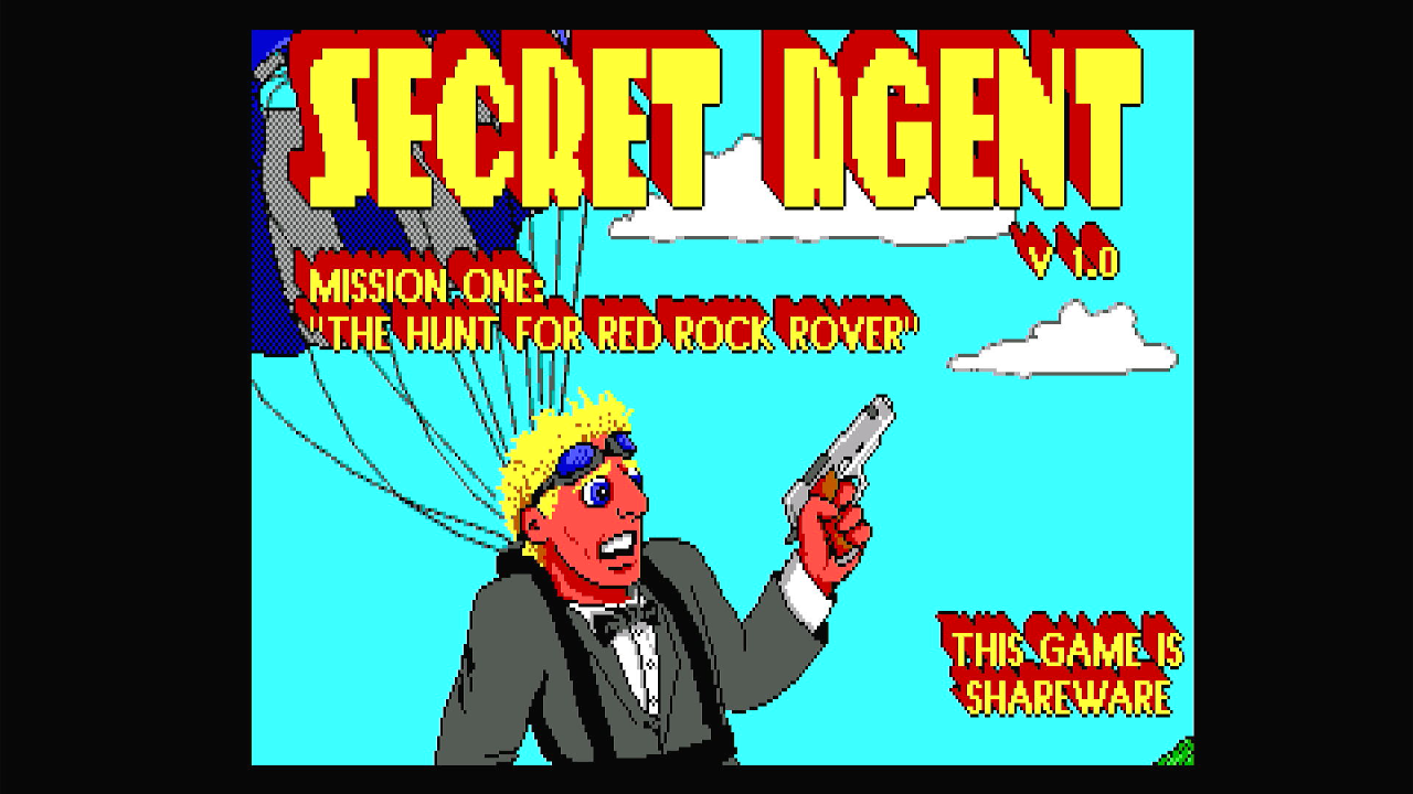
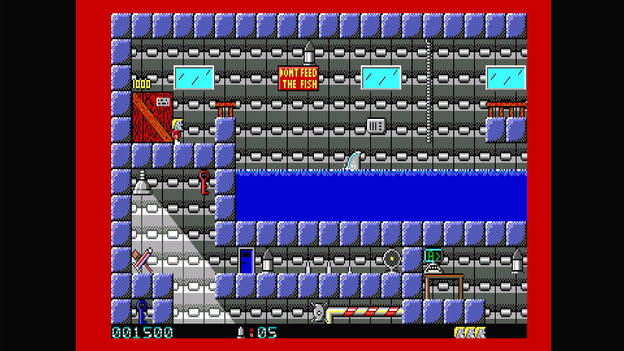
Secret Agent suffered the same scrolling glitches that we see on games like the Commander Keen series - this is down to the Octek graphics card, not the RGBtoHDMI, which looked amazing.
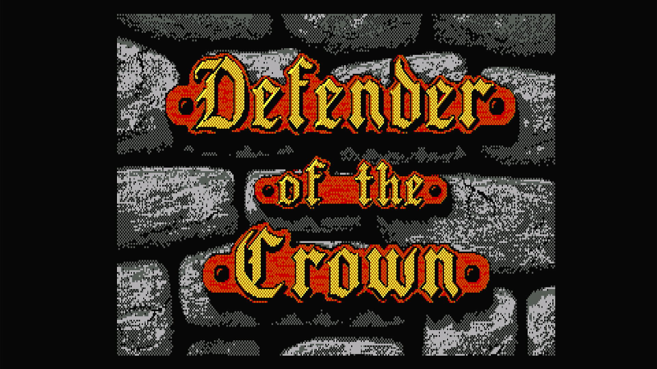


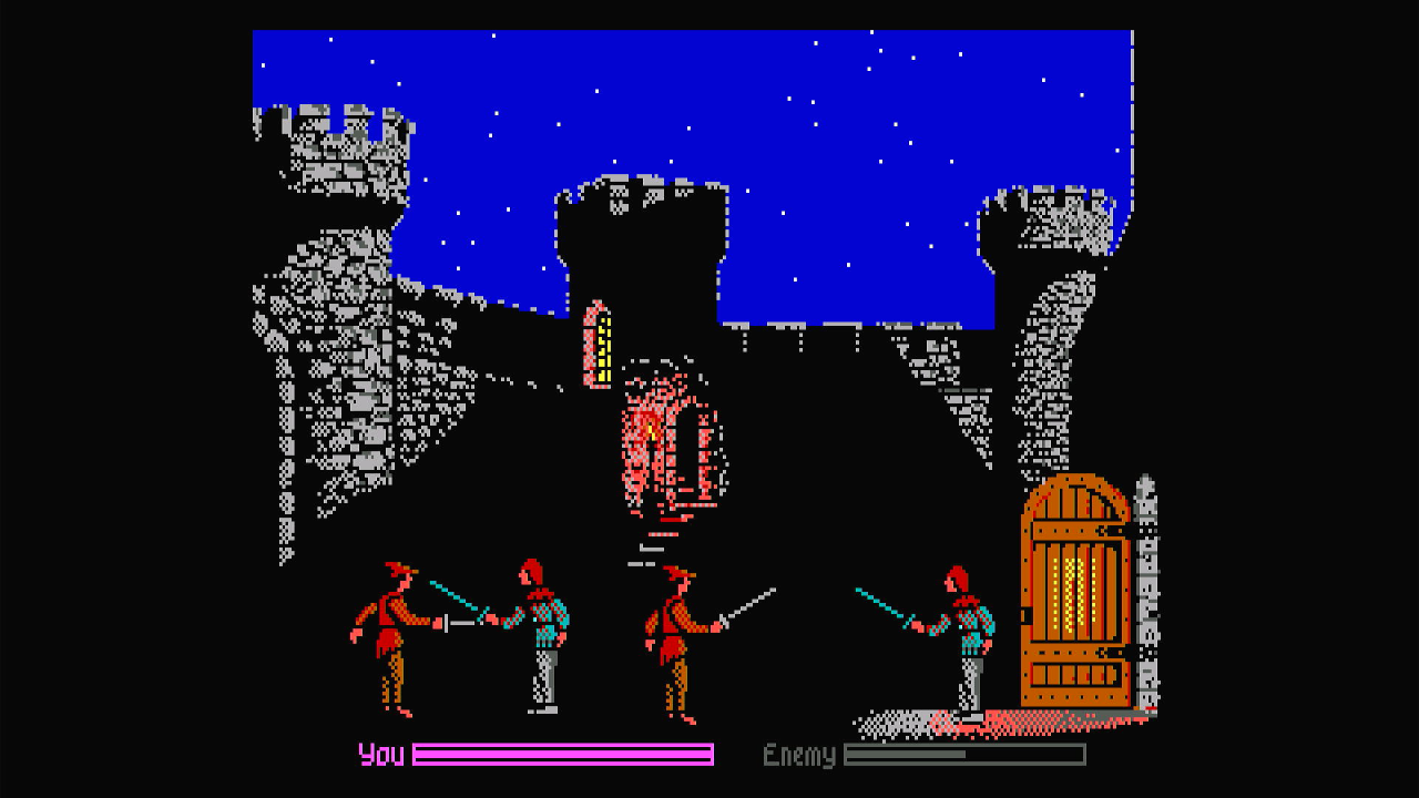
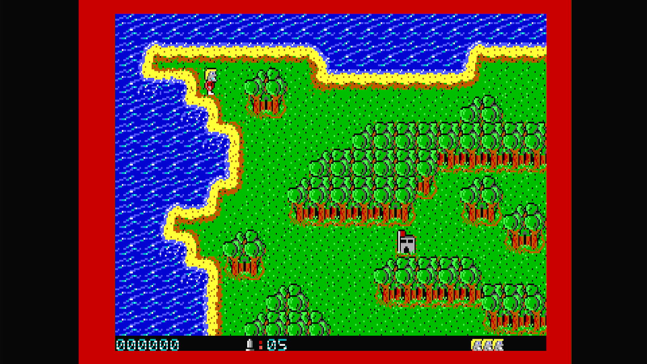
Defender of the Crown always looked amazing, and still does through the RGBtoHDMI - no issues.
Railroad Tycoon ran well without any issues. Colours look great and scaled very nicely.
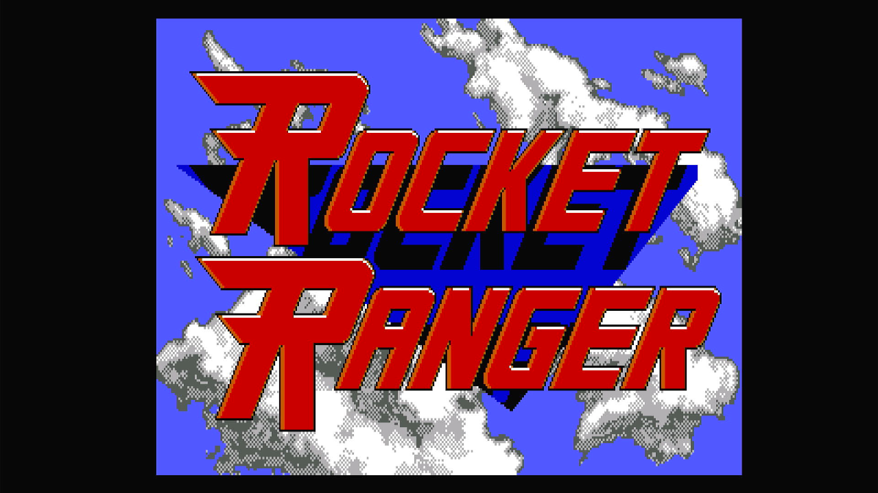
Rocket Ranger also played really well through the RGBtoHDMI.
Initial Thoughts
I played with some of the RGBtoHDMI's settings, including switching from integer scaling to interpolation as well as changing the resolution. The former showed very little change - the quality was still really good with interpolation scaling compared with the pixel-perfect integer scaling, though my testing was far from exhaustive. Changing the resolution was easy - I've been running in 1920 x 1080, (since that's what my Full-HD monitor defaults to), and that is why we have the two large black bars down each side of the converted image. By making the resolution 640 x 480, say, this stretches out the image on the monitor to fill it. Setting it to 'Auto' most likely talks to the monitor via its DVI or HDMI protocol to request its native resolution, and sets it accordingly. In my case, this chose 1920 x 1080 at 60 Hz. Each resolution change requires a reboot of the RGBtoHDMI (unlike most other settings that it can handle on-the-fly).
On the whole I am very impressed with this little device, especially given its low price point. I don't own an OSSI or other more premium scaler/converter, though I do hear they are the best you can get (if you can afford it!). The RGBtoHDMI provides you with a lot of flexibility and high quality output for such a low price, it's likely I will be using it for many future projects that involve the earlier PC graphics standards.
In Part 2, I will switch out the Octek EVGA-16 EGA card for some other cards, including CGA and Hercules.