Retro Review - Faraday Micro PC
7th November 2023
Introduction
One of my regular contributors, Andrew Welburn from Andy's Arcade recently acquired this single board computer designed around the Faraday FE2010A chipset:
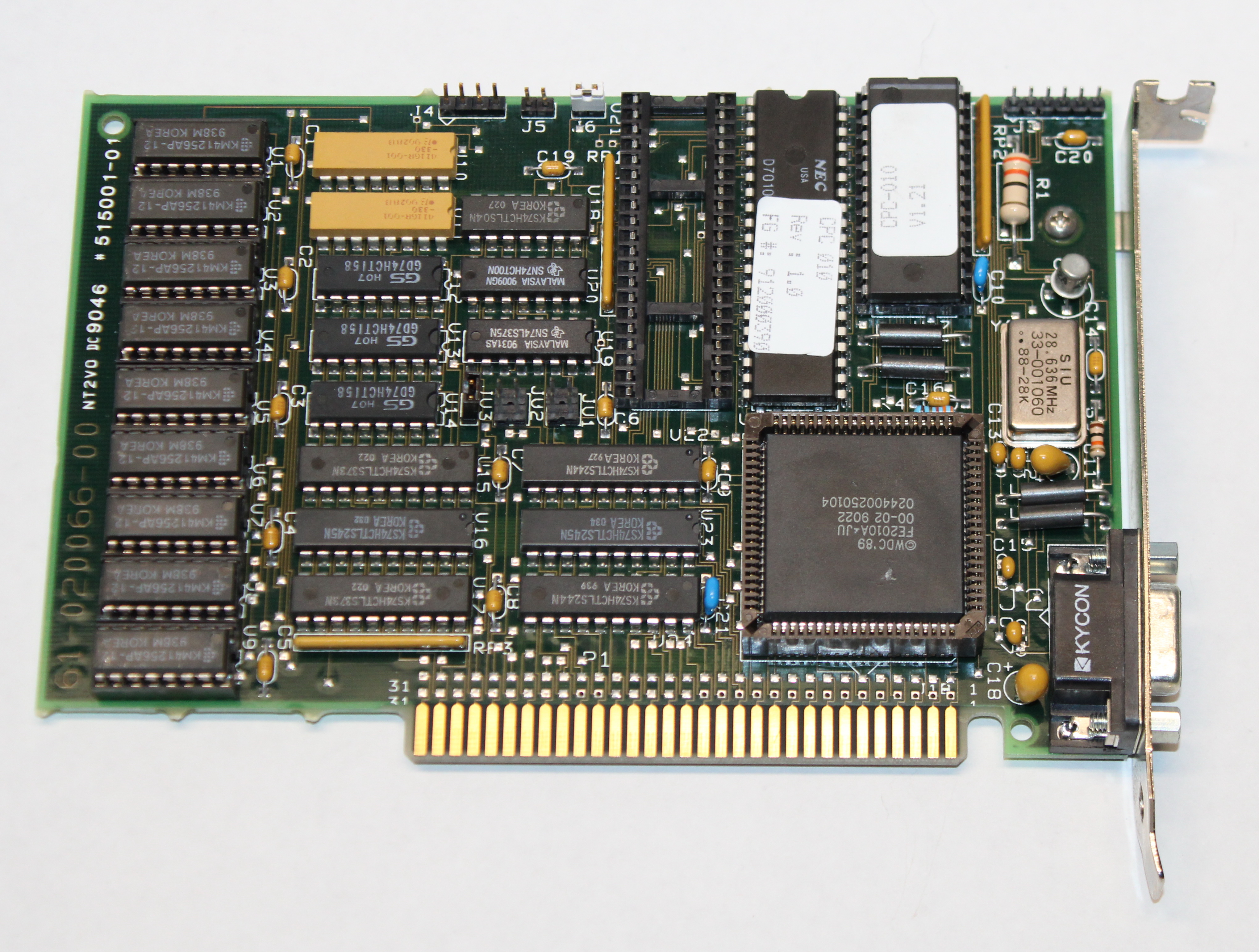
Faraday MicroPC
A single board computer, or SBC, is just as it sounds - it's an entire computer on a single card, comprising CPU, chipset, BIOS, clock generator, and memory. Typically, these would have been connected to a base PCB called a backplane. A backplane was usually a very elementary board with a power connector and one or more expansion slots, into which you would connect the SBC (and any other expansion cards you had). Some PC manufacturers used this design approach instead of the more common integrated motherboard design where all of these chips sat on the same PCB as the expansion slots.
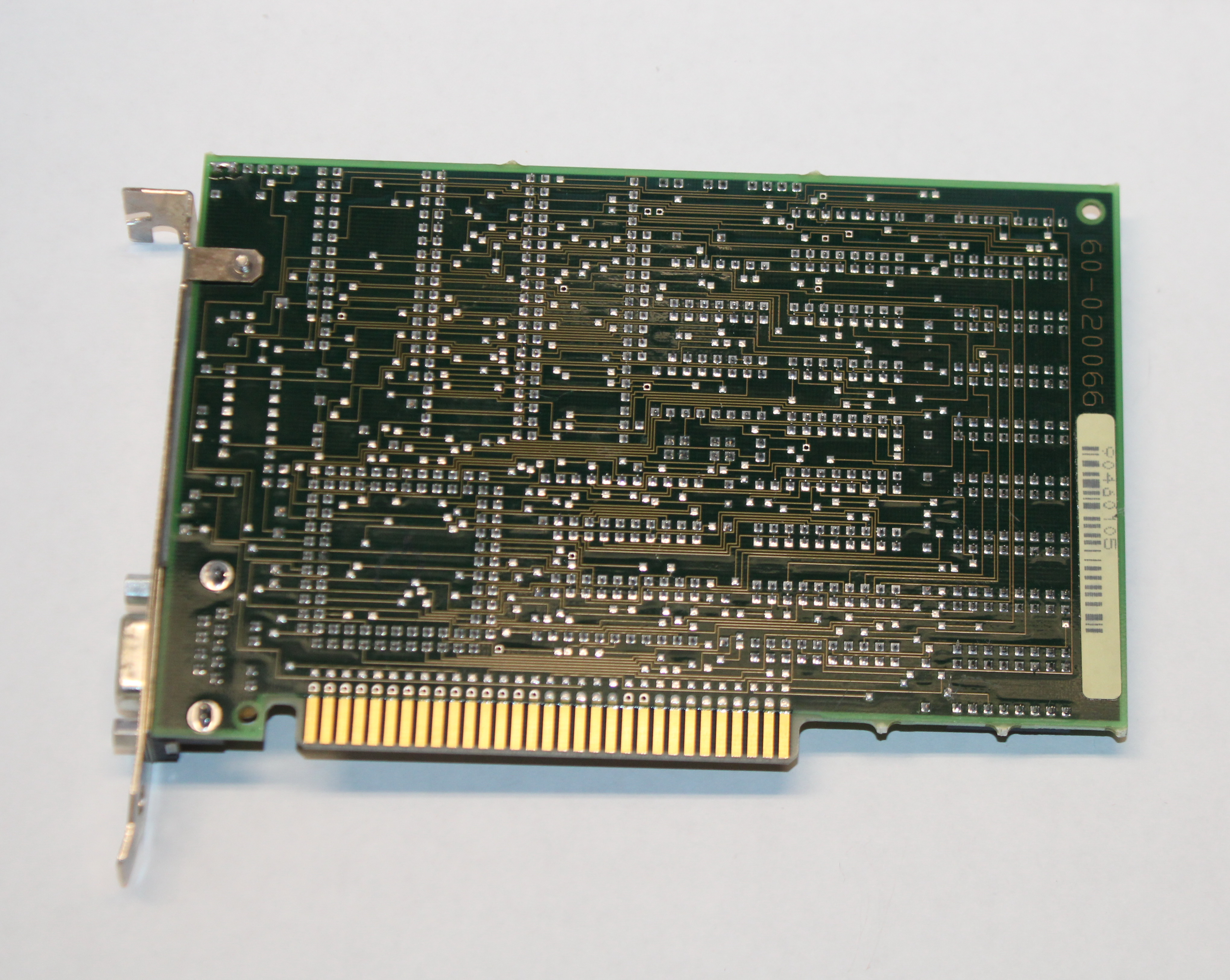
Quick Visual Inspection
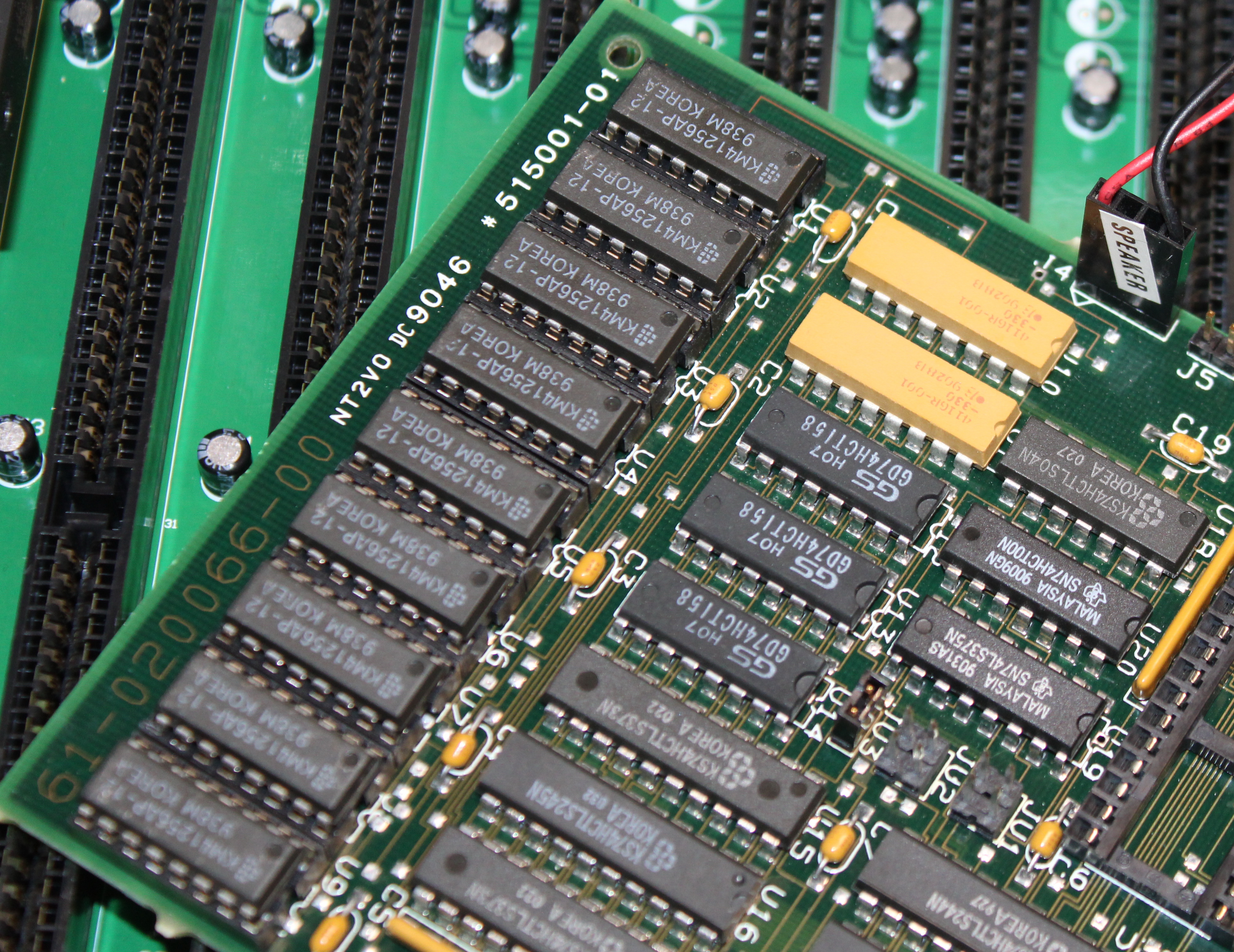
As you would imagine, the card is jam-packed, given that it's got almost everything needed to be a complete PC board:
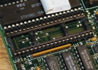
- Faraday FE2010A chipset
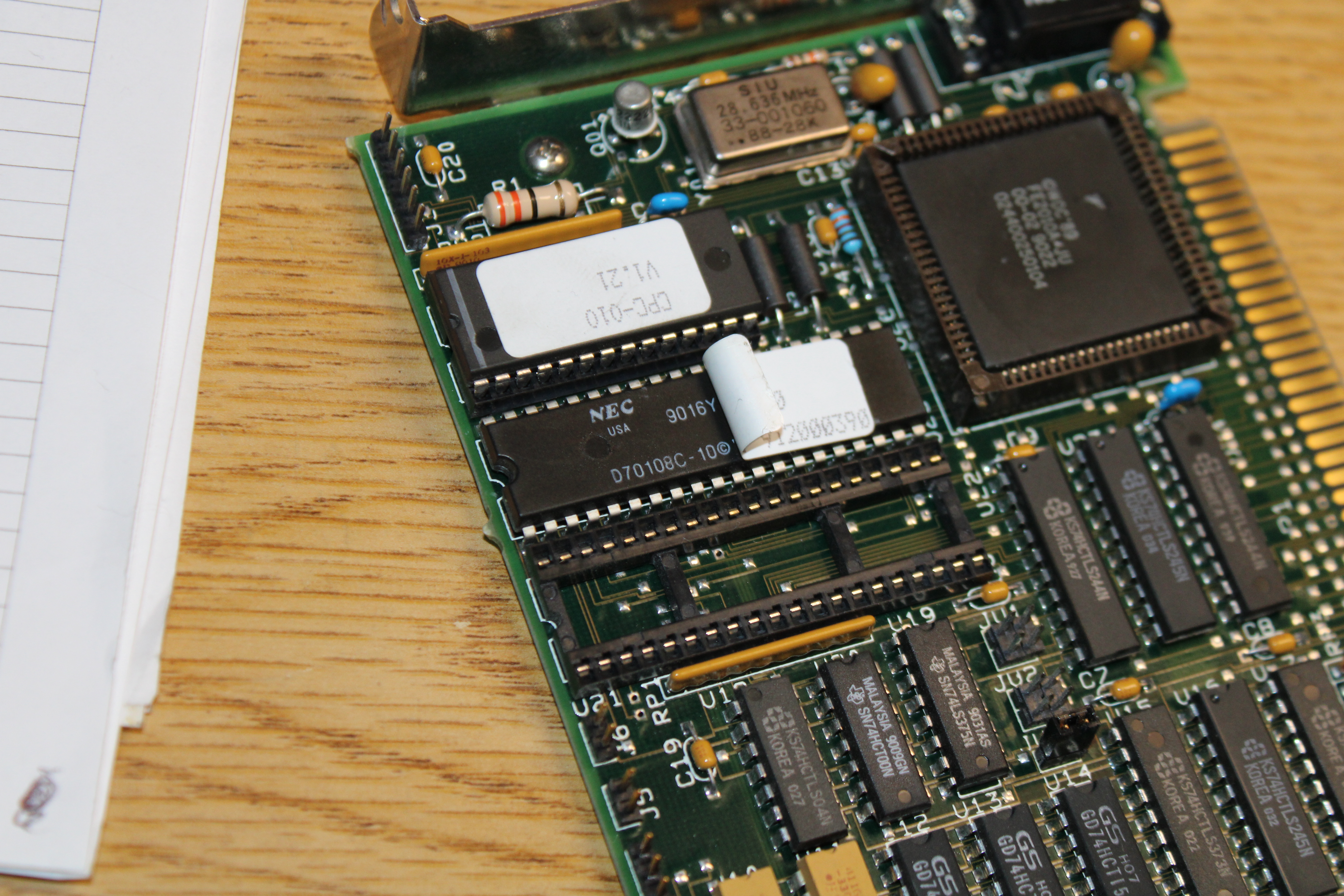
- NEC D70108C-10 (V20) CPU
- 26-pin BIOS chip
- A socket for Intel 8087 math coprocessor
- A 28.636 MHz crystal oscillator
- 9 DRAM ICs (Samsung KM41256AP-12)
- A female DB9 port on the backplate
- A 6-pin header at J3
- A 4-pin header at J4
- A 2-pin header at J5
- A shorted 2-pin header at J6
- An 8-bit ISA expanion bus edge connector at the bottom
The Component Parts
The Chipset
 I covered this chipset in detail in another dedicated article, but to summarise, the Faraday FE2010A was a single-chip chipset for XT machines. The chip itself is a 2 micron CMOS gate array with 84 pins and is in a J-leaded PLCC (Plastic Leaded Chip Carrier) package.
It was an enhanced version of their earlier FE2010 controller but with added support for a Turbo mode, i.e. higher clock speeds. The chipset implements all of the Intel 8xxx supporting ICs (excluding the CPU and FPU) as well as all the glue logic chips found on the IBM XT motherboard, including the Intel 8288 Bus controller, Intel 8042 Clock generator, Intel 8259A Interrupt controller, Intel 8237A DMA controller and Intel 8253 Timer.
The CPU
 The microprocessor on this single board computer is an NEC V20 running at 10 MHz. The V20 was pin-compatible with the Intel 8088, but had more enhanced circuitry that made it about 20% more efficient at running instructions. It also incorporated the instruction set of the Intel 80186 CPU and could be put into a special Intel 8080-emulation mode, where instructions could be given to execute programs written for the Intel 8080 processors.
It was a popular upgrade choice for IBM 5150 owners looking for a cheap way to eke out a little better performance from their PC.
The BIOS
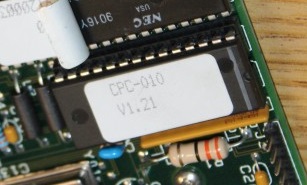 The BIOS chip is a 26-pin EPROM with the marking "CPC-010 V1.21". The sticker might be covering up a UV-erase window, though later EPROMs were electrically-erasable instead.
According to the 1986 Faraday OEM Catalogue, "the board contains up to 64K of EPROM memory and supports 2764, 27128, 27256 and 27512 EPROM chips. The top 64K of memory (address FEO00 to FFFFF) is reserved for the EPROM memory. The top 8K of ROM memory is reserved for the Faraday BIOS, support for the user installed program in the remaining 56K is provided for in the BIOS. The memory cycle is 840ns and the access time is 250ns". Andrew confirmed it's actually a masked ROM - a Signetics 27C256.
Coprocessor Socket
 A 40-pin socket for an optional math coprocessor was a common sight on XT motherboards, and this is no exception. These early CPUs did not have dedicated floating point instructions, so the CPU had to do all the work of number crunching. With a math coprocessor, aka floating-point unit (FPU), these instructions would be offloaded onto the coprocessor, leaving the CPU to be able to process non-floating point operations.
Math coprocessors were not hugely popular unless you were using math-heavy applications like CAD software, though spreadsheets like Lotus 1-2-3 did support them also. Intel's 8087 was the supporting coprocessor for the Intel 8088 and NEC V20 CPUs. Because the coprocessor was driven at the same clock speed as the CPU it was important to have one that could support that clock speed, in this case, 10 MHz. Math coprocessors ran pretty hot and did not overclock well.
Crystal Oscillator
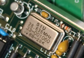 A single crystal oscillator is required to provide the clock signals to the CPU and chipset.
The frequency here, 28.636 MHz, gives the board the capability to run in a CLK/3 divider, meaning the CPU and chipset would receive an actual clock of 9.54 MHz. By default, Andrew confirmed this board defaults to a boot up clock speed of 4.77 MHz - you need to run the setspeed utility to get it running at 7 or 9.54 MHz.
Memory
 The onboard memory consists of nine 16-pin DRAM chips. The odd number implies eight of these were used for the main memory with the ninth as a memory parity chip (for error correction).
The DRAMs used here are Samsung-branded KM41256AP-12, which are 256K x 1-bit Fast Page Mode (FPM) Dynamic RAM with a 120-nanosecond access time. This gives the board 256 KB of memory.
According to the Faraday 1986 OEM Catalogue, the board can be upgraded with an additional 384 KB via an expansion slot (on the backplane). Presumably any memory expansion card would need to be configured to 'start' from the 256 KB mark, as the Micro PC's onboard memory would most likely take up the first 256 KB of base memory first. Andrew added "So far I have not been able to get additional RAM cards to be detected on the bus. I'm not sure on the purpose of the jumpers in the middle of the board, if these are responsible. There is a register to write to in order to set the RAM size, but I'm not sure how that's supposed to be set before boot so it looks for more RAM. I don't entirely understand this RAM sizing method so far :)"
DE9 Port
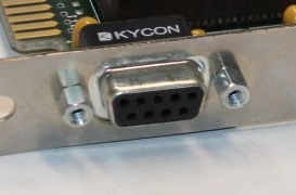 Andrew and I were confused by the DE9 port on the backplate of this single board computer. Logic would have you believe this is a video-out port - something like Hercules monochrome or perhaps CGA-compatible - but there does not appear to be any video circuitry on the board, and the FE2010A does not have any built-in video-out capability.
Andrew writes: "When I was tracing signals for the pin header for the keyboard, the CLK and Data lines also ran to this DE9 port through ferrules. When I read the brief manual, it also mentions the DE9 port is for a keyboard. I have yet to ever see a keyboard with a male DE9, but I assume this is a more rugged and easily made/used keyboard connector that is accessible on the 'outside' of an enclosure or case that the card might be put in, given it's potential to be used in industrial applications."
The Micro PC was designed to be used with a backplane, so adding your own display card into another slot on the backplane will provide video output. Faraday themselves offered the Micro PC in "Evaluation Systems" which contained their FE-5200 Monochrome Display Controller card (in addition to floppy drives and a keyboard).
Headers
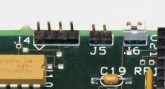 As mentioned, there are four pin headers at the top of the board. These are used as follows:-
J3 (6-pin) is the keyboard connector - being an XT board this is only compatible with the IBM PC/XT keyboard controller (which is unidirectional, as opposed to AT keyboards that are bidirectional). If you have an AT keyboard you will need to buy or create an AT-to-XT keyboard converter. On this header, pin 1 is CLK, pin 2 is Data, pin 3 is unused, pin 4 is GND, pin 5 is unused and pin 6 is +5V.
J4 (4-pin) is the speaker connector, with pin 1 as Audio-out and pin 4 as GND. Pins 2 and 3 are not connected.
J5 (2-pin) is for a reset switch.
J6 (2-pin) can be used to generate an NMI (Non-Maskable Interrupt) externally.
Expansion Bus Connector
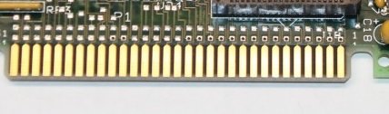 The Micro PC is designed to be used with a backplane, and receives all its power via the expansion bus (+5V at 0.5A for the NMOS version, and +5V at 150ma for the CMOS version). Faraday Electronics at the time offered a six-slot PC BUS backplane or an eight slot AT BUS backplane.
Connecting it Up
Andrew purchased an ISA backplane in order to get this single board computer operational:
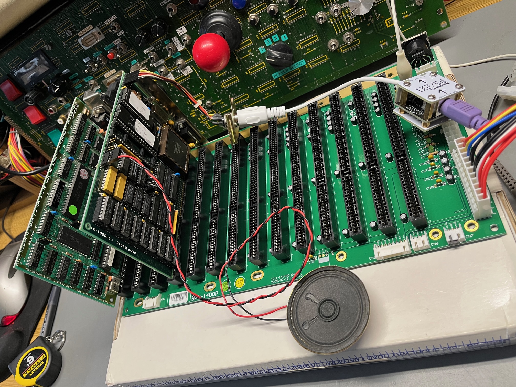
ISA Backplane with fourteen 16-bit ISA slots and AT (P8/P9) power connectors.
Unrelated, but also check out that arcade board behind - nice!
The card you see to the left of the Micro PC is a Hercules-compatible graphics card. He connected up a speaker to J4 and wired the 6-pin keyboard header at J6 to a DIN connector, and from there into a PS/2-to-XT keyboard converter box in order to use a more modern-day PS/2 keyboard with this PC.
With the two AT power connectors plugged into the backplane, it was time for power-on!
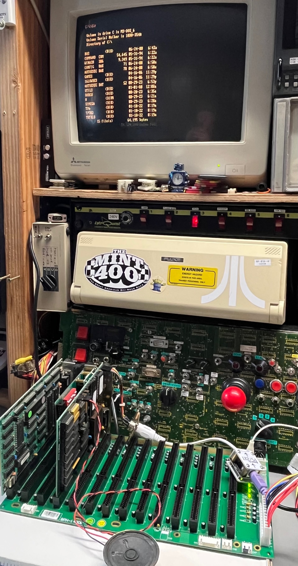
It lives!
With the CPC-010 BIOS, Andrew told me there is no BIOS copyright message that appears on startup. Just the memory test count from 0 - 256 KB and that's it.
Initial Testing
Andrew noticed that the SBC here does not run at the full 9.54 MHz turbo mode, and determined that jumper J6 that was thought to be for a turbo switch does nothing. He sourced a utility called SETSPEED.EXE which was written for the NuXT PC and uses the same chipset. It worked a treat on this SBC!
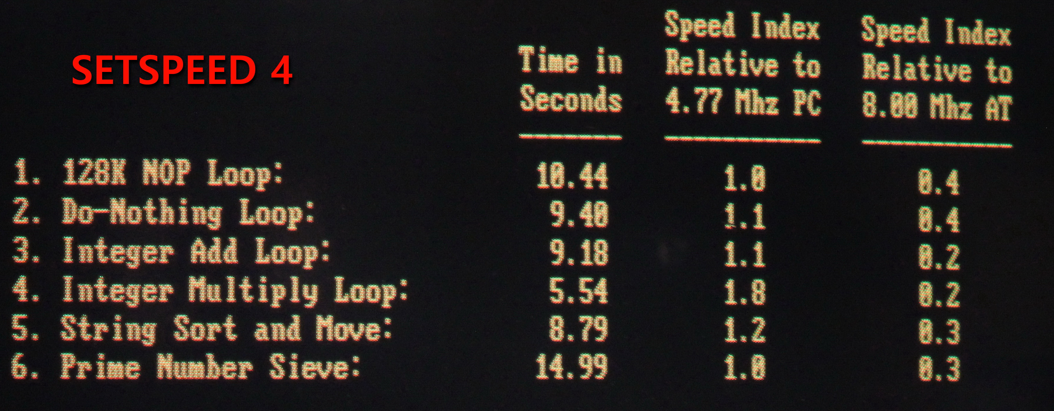
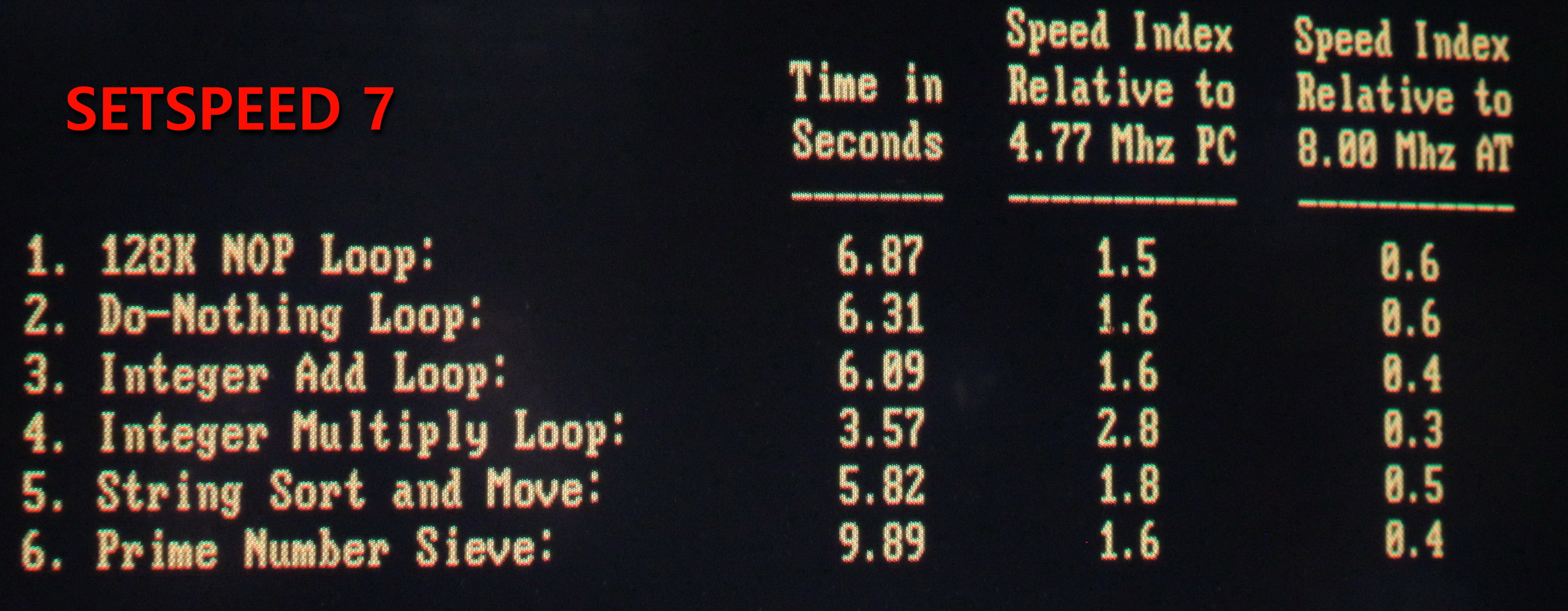
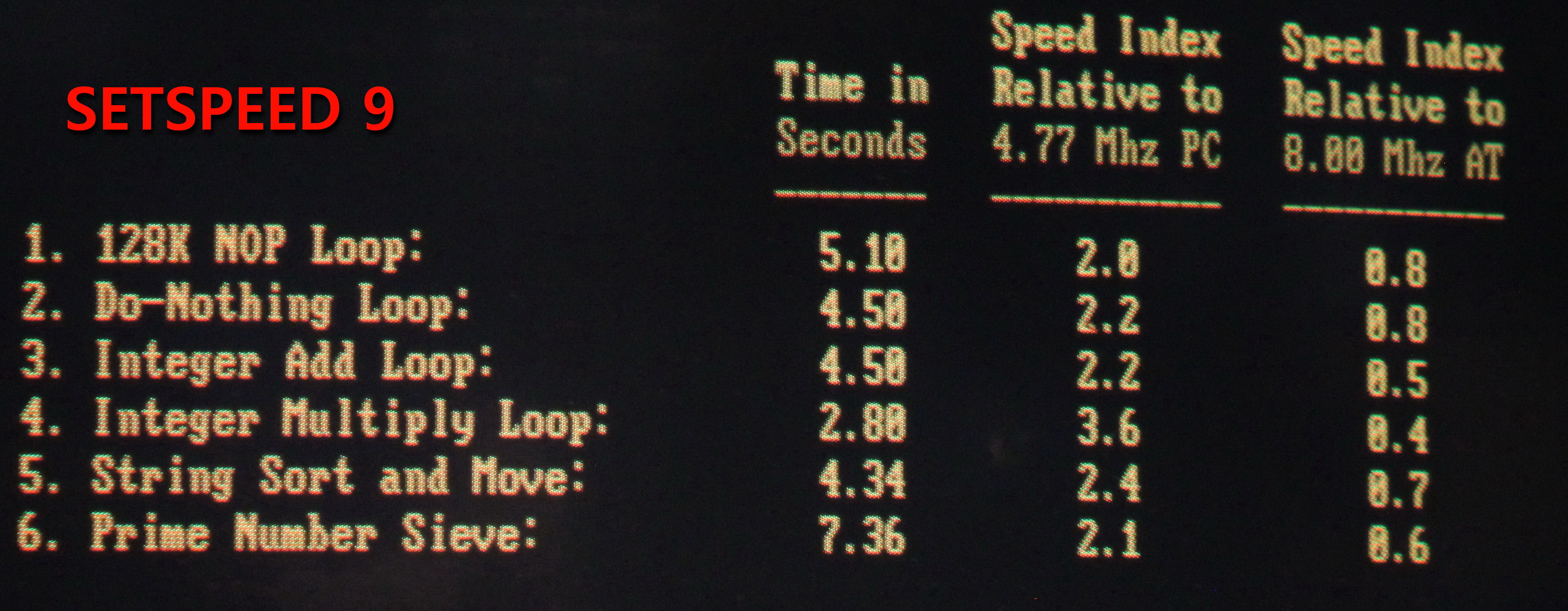
SETSPEED results running at 4.77 MHz, 7 MHz and 9.54 MHz
ROM BIOS
Andrew took a dump of the "CPC-010" ROM BIOS, which can be downloaded here. This is apparently just Faraday's own standard BIOS provided with the Micro PC.
An alternative BIOS that would likely work (and by default start with the full 9.54 MHz clock speed) is the one from my original PC/XT clone which uses the same FE2010A chipset, NEC V20 and 640 KB of RAM. That motherboard was a Taiwanese one called Peter-10 or P-10. The BIOS is called the ZETA P-10 BIOS. Download it here.
The GitHub GlaBIOS project also has a BIOS ROM that is compatible with the Faraday FE2010A chipset. This project is "A modern, scratch-built, open-source alternative BIOS for vintage PC, XT, 8088 Clone or Turbo PCs." and are designed to replace the BIOS in a good number of PCs, XTs and compatibles. Lots of enhancements have been written into these BIOS - the latest version for the FE2010A at the time of writing this article is version 0.25_VF for NEC V20-based systems and version 0.25_8F for Intel 8088-based systems.
Conclusion
It's great to see an old and interesting single board computer once again operational. Special thanks to Andrew Welburn for providing the details of this project and all of the images above. Be sure to check out his website at Andy's Arcade for all your arcade machine components or just to view his amazing collection!