CRT Monitors
Introduction
This page provides details on the various monitor technologies used with DOS PCs. It should be read in conjunction with the Graphics Cards page for completeness. This page uses the term 'display card' as a more generalised term for 'graphics card', as it includes cards that can only display text as well as later cards that produce both text and graphics. Also, if you're interested in laptop/portable PC screen technology, head on over to my laptop displays page.
Before the modern day of LCD / LED televisions and monitors, we had CRT (Cathode Ray Tube) displays. These were necessarily bulky due to the fact an electron gun that fired a beam at the back of a display area needed to be positioned far back from the actual surface of the display itself. CRTs, for all their girth, do still have some advantages over modern flat screens. CRTs don't suffer from dead pixels, they have a better viewing angle, and of course have retro authenticity (adjacent pixels blurred together more) - the fact that running old software on modern screens looks decidedly odd, showing up the low resolutions that existed back in the day - this is not as noticeable when viewed on a CRT monitor it was designed for. But I digress... let's take a journey through the various display technologies of old....
From left: Monochrome/MDA/Hercules, good for hi-resolution text in 2 colours (pre-1984)
RGB Colour - CGA-compatible 4 colours at 640x200 or 16 colours at 320x200 (pre-1984)
EGA-compatible 16 colours at 640x350 (1984)
PGC-compatible 256 colours at 640x480 (1984)
VGA-compatible 256 colours at 640x480 (1987)
Multiscan monitors that support all standards (1987)
It is worth noting that all of these monitors were designed for an aspect ratio of 4:3 (compared to 16:9 or 16:10 today), so running a resolution of 320x200 meant some 'letterboxing', or the monitor would stretch the image vertically to fill the screen. Because this resulted in non-square pixel blocks, many games designers / artists worked around this to ensure their images didn't appear like they were "stretched".
Monitor Specs to Look For
The specifications you would have looked for when deciding on a monitor to purchase include physical size, frequency range, dot pitch and refresh rate. Things that weren't important were contrast and brightness (something that became much more critical on LCD/LED displays later on), as these could be controlled directly via control knobs on the monitor.
Physical Size
The physical size of the display area was measured diagonally from top-left to bottom-right (or bottom-left to top-right), and was almost universally shown in inches. A 10" or 12" display was about the minimum, and this size was common on monochrome (MDA and Hercules) monitors. CGA and EGA monitors were produced mostly in 12" and 14" sizes. VGA monitors started out at 13" and 14" but went up to 15", 17", 19", 21". Is wasn't uncommon for manufacturers to advertise their monitors as 1 inch larger than the actual visible display area - they got around the legalities of this because strictly-speaking they are telling you the diagonal size of the picture tube and not all of it is usually able to be shown.
Frequency Range
The frequency range really only became significant once Super VGA arrived which allowed you to run programs in higher resolutions while also needing to support older software that ran in lower resolutions. All monochrome, CGA, EGA and VGA monitors were "fixed-sync", meaning they could only take in a video input signal at one horizontal sync frequency. More acurately, EGA and VGA monitors usually supported two horizontal sync frequencies, since EGA cards output at 18 kHz for 640 x 200 and lower resolutions, and 21 kHz for 640 x 350 resolution. These though were still considered 'fixed sync' though. VGA operates at a fixed horizontal frequency of 31 kHz, and Super VGA defined by the VESA standard runs at 48 kHz.
Multisync or Multiscan monitors arrived after VGA was established, and automatically scanned the input signal to set the monitor's frequency correctly. These were much more expensive, and gained popularity as Windows display resolutions went higher and higher. Most multisync CRTs only supported VGA horizontal frequencies and higher (you need a higher frequency as the screen resolution increases), so older PC video display standards (MDA/Hercules, CGA, and EGA) would usually not work on these monitors. However, there were a number of monitors that had a wider range of horizontal frequencies it would work with, from 15 kHz and up. Note however, that from VGA onward, graphics cards output analogue signals, whereas MDA/Hercules, CGA and EGA all output digital signals. All VGA and mulitsync monitors take analogue inputs, but some multisync ones also accept digital video inputs as well.
Dot Pitch
A CRT's dot pitch, measured in millimetres (mm), tells you the distance between the red, green and blue dots that make up each pixel. The smaller the dot pitch, the sharper or finer the image will be. Dot pitch specs weren't usually mentioned on CRT monitors prior to the VGA standard. Common dot pitches for a VGA monitor were 0.41mm, 0.31mm, 0.28mm and 0.26mm.
Refresh Rate
A CRT monitor's refresh rate is the 'speed' at which the monitor can refresh the entire display area with the latest video contents sent to it by the graphics card. Higher screen resolutions means more information needs to be sent to the monitor - this often meant the maximum refresh rate the monitor could handle would reduce as the screen resolution increased. Coupled with refresh rate was the concept of interlaced and non-interlaced. Interlacing was a technique of drawing the screen every odd row in the first pass followed by every even row in the next pass. This would often result in the screen appearing to flicker slightly. Non-interlaced is probably what we called 'progressive scan' these days, where the entire row of pixels is drawn in a single pass, resulting in far less flicker. CRTs could usually manage to display a higher refresh rate in interlaced mode and a lower refresh rate in non-interlaced mode. Typical refresh rates range from 60 Hz up to over 100 Hz on these CRTs, where the higher the refresh rate the less flicker and more stable the image appears to be. The standard defined by VESA for 800 x 600 Super VGA was to run at a vertical refresh rate of 72 Hz, and at 60 Hz for 1024 x 768.
MDA and Hercules Monitors
From the first IBM MDA (Monochrome Display Adapter) card up to the EGA standard, all PC video output was digital which required connection to a monitor that accepted a digital signal input. With MDA, each character is displayed in a "cell" of 9x14 pixels, of which 7x11 depicts the character itself and the rest is used for spacing between character columns and lines. The theoretical total screen display resolution is 720 x 350, however the MDA card cannot address individual pixels (it's text-only), making it a "display card", not a "graphics card".
Hercules Computer Technology introduced their Hercules Graphics Card (HGC) in 1982 as an upgrade to IBM's MDA standard. It supported a bitmapped graphics mode in addition to the high quality text mode offered by MDA. The graphics mode was 720 x 348, and used the same horizontal and vertical scan frequencies as MDA, which meant existing MDA monitors supported the Hercules card out-of-the-box. Compatibility of HGC to MDA was so good that when running in text mode (its default on startup), a PC couldn't tell the difference and assumed it was an MDA card. Hercules HGC cards also output digital TTL signals, just like MDA.
You can be almost 100% sure that if your display card has a 9-pin D-SUB female connector, it's outputting digital signals. These signals use what's called TTL (Transistor-Transistor Logic), which outputs a HIGH (+5V) or a LOW (0V) depending on whether to fire the CRT eletron beam or not. Also in the MDA video output is an intensity signal (for brightness of characters) and separate horizontal and vertical sync signals.
An MDA card's female 9-pin DSUB output connector and its pinouts
(so pin 1 is in the top-left of a male 9-pin
connector on the cable)
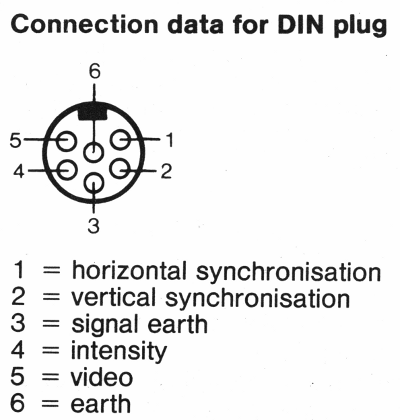
On the monitor side will be either a round DIN socket or a 9-pin female DSUB (just like on the display card).
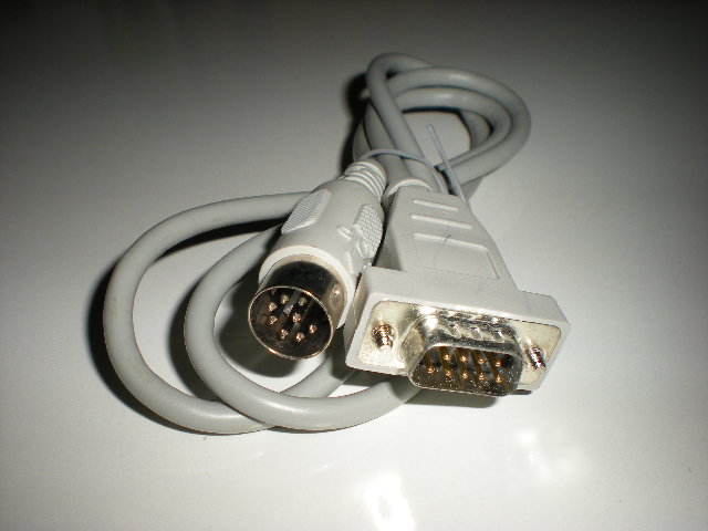
A digital mono video cable that connects an MDA or Hercules graphics card to a mono monitor
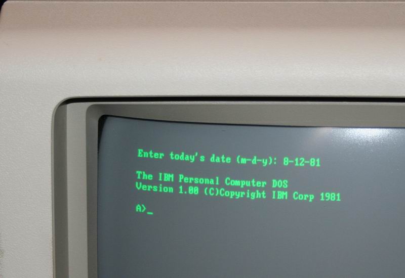
Monochrome monitors displayed either green, amber, or white characters on a black background. A monitor that displayed green did so because it used green "P1" phosphor to light up each pixel on the display. Old monitors tended to have a very low refresh rate (the speed at which the entire screen's contents were refreshed with new content based on data coming from the display card). Green phosphor had the longest "afterglow" of the three, so it remained "lit up" on the screen for longer between refreshes, and green is the brightest type of phosphor. This also made it a cheaper monitor to build. "Green screens" were hugely popular in the early days of the PC, and could still be bought brand new with a complete system 10 years later!
The various monochrome PC display "colours" of green, amber and white!
Amber monitors came a little later, and used what's called "P3" phosphor. It was considered easier on the eyes for business use but required a faster refresh rate as it stayed lit for a shorter time - these amber monitors were more expensive to manufacture.
Black and white monitors displayed white or grey characters on a black background, and used what's called "P4" phosphor. These were sometimes referred to as "paper white" displays.
Strangely, when purchasing a PC in the 1980s and early 1990s that had a monochrome display, you were rarely informed of the "colour" you would receive. Instead, it was simply referred to in advertisements as a mono (or monochrome) monitor.
CGA and EGA Monitors
CGA monitors arrived on the scene in 1981, coinciding with IBM's launch of the Color Graphics Adapter (CGA) card. This permitted up to 4 colours to be simultaneously displayed on-screen (not including black) at a resolution of 640 x 200 pixels. It also provided the option of 16 colours (its full palette) at 320 x 200 pixels. CGA monitors operated at a scan rate of 15.75 kHz.
The EGA standard, introduced in 1984, expanded on this with up to 16 colours at a resolution of 640 x 350 pixels. This was from a total palette of 64 colours. After EGA arrived, an inexpensive PC clone that supported EGA graphics could produce better graphics than rivals at the time including the Commodore 64 and Apple II. Text characters were made up of 8 x 14 pixels instead of CGA's 8 x 8. EGA monitors ran at a scan rate of 21.85 kHz, but since EGA was a superset of CGA (fully backward-compatible) they could also scan at CGA's frequency of 15.75 kHz, though it was sometimes necessary to set a DIP switch on the monitor to tell it to operate at CGA frequency. By 1987, EGA monitors were averaging around $700, with a typical diagonal screen size of 13", and having a dot pitch of between 0.28mm and 0.40mm (the lower the dot pitch the more fine the picture quality).
Both CGA and EGA send their signals as digital TTL, just like MDA and Hercules. The previously unused pins in the same 9-pin DSUB that was used by MDA and Hercules were now employed by CGA and EGA cards to transmit the red, green and blue colour (plus intensity) information to the supporting monitor:
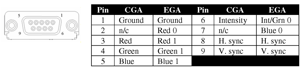
A CGA or EGA card's female 9-pin DSUB output connector and its pinouts
Note: Red 0, Red 1 and Green 1 are the "Primary" colour signals, whilst Red 0, Grn 0 and Blue 0 are the "Secondary" colour signals. The primary signals provide the actual colour whilst the secondary signals provide the "intensity" of the colour.
If you connect an EGA card to a CGA monitor it should work if the EGA card is outputting at the same scan rate as CGA (15.75 kHz) and the monitor isn't running pin two to ground which would short out the EGA card and potentially damage it. Check your EGA card's manual to be sure it can output at the CGA frequency and set the EGA to work in this mode before switching on your CGA monitor! All EGA video modes that support 200 lines operate at this lower scan frequency of 15.75 kHz. Most EGA cards have DIP switches on the side to set the monitor type.
PGC (Professional Graphics Controller)
Back in September 1984, IBM launched two new graphics standards: EGA and PGC. EGA we all remember, but PGC? Not so much! The Professional Graphics Controller was designed to be used for computer-aided design (CAD) and other high-end graphics applications for business. It supports a maximum screen resolution of 640 x 480 with 256 colours on-screen from a palette of 4,096.
The IBM PGC card retailed for around $3,000 and the monitor (called the Professional Graphics Display or PGD) for $1,300, so financially it was far from the reach of the typical retail PC buyer. Unlike previous display standards, PGC output an analogue signal, and the PGD monitor operated at a horizontal refresh rate of 30.48 kHz.
PGC and associated monitors that supported it were a flop. The resolution wasn't much better than EGA, the card ran extremely slowly, took up two expansion slots in your PC, and all at a sky-high cost of $4,300. Very few software vendors wrote drivers to support PGC due to the low take-up, and not long after its arrival, numerous graphics card manufacturers were coming out with "Super EGA" cards such as the VideoSeven VEGA Deluxe and ATI EGA Wonder 800 which offered 640 x 480 resolutions, though only still at 16 colours.
VGA and Beyond
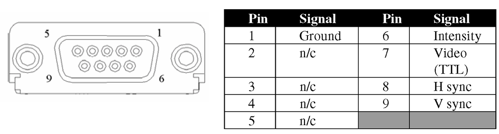
With the advent of the VGA graphics standard in 1987, the output of VGA graphics cards moved from digital to analogue in order to support the seemingly infinite number of colours the VGA standard could support. If your graphics card has a 15-pin D-SUB female connector, it's almost certainly outputting analogue RGB (Red, Green, Blue) signals. More specifically, they carry RGBHV (Red, Green, Blue, Horizontal Sync, Vertical Sync) signals. These connect to an "analogue" monitor, which accept these analogue RGB signals and convert them back into digital signals to know how to display the colour on the screen.
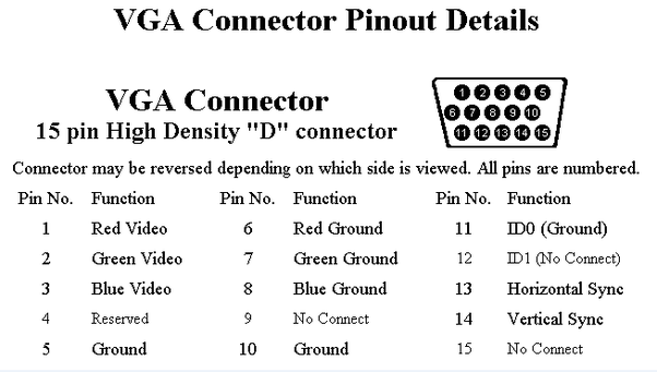
A VGA monitor's female 15-pin DSUB output connector and its pinouts
It's worth mentioning that mono VGA is different - it only needs 8 or 9 wires but the signalling is completely different to MDA (Mono TTL is 5V digital whereas VGA is 1V analogue). Monochrome VGA monitors were common in laptops but also some desktop PCs. These typically offered up to 16 "greyscales" to replace the colours.
VGA monitors differ from Super VGA monitors, as they only support the VGA standard's maximum resolution of 640 x 480. Super VGA monitors arrived in 1988 and added support for 800 x 600 some went up to 1,024 x 768. All these are still "fixed sync" monitors, operating at the VGA horizontal sync frequency of 31 kHz. It was very common for computer retailers to bundle a monitor with the PC you were buying, so it was important to understand if the monitor was "VGA" or "Super VGA".
Here's a short list of some VGA and Super VGA monitors that were being sold around 1991:
| Make/Model | Type | Size | Dot Pitch | Highest Resolution @ vertical refresh rate | Price | Notes |
|---|---|---|---|---|---|---|
| IBM Color Display 8512 | VGA | 14" | 0.41mm | 640 x 480 | $623 | |
| IBM Color Display 8513 | VGA | 12" | 0.28mm | 640 x 480 | $750 | |
| IBM Color Display 8515 | SVGA | 14" | ? | 1024 x 768 interlaced | $950 | |
| Compaq Video Graphic Color Monitor | VGA | 14" | ? | 640 x 480 | $699 | |
| Compaq Advanced Graphic Color Monitor | VGA | 16" | ? | 640 x 480 | $799 | |
| Zenith ZCM-1492 | VGA | 14" | ? | 640 x 480 | $999 | |
| Packard-Bell PB8528SVG | SVGA | 14" | 0.28mm | 1024 x 768 I 800 x 600 NI |
$899 | |
| Packard Bell PB8509VG | VGA | 14" | 0.28mm | 640 x 480 | $729 | |
| Packard Bell PB8539VG | VGA | 14" | 0.39mm | 640 x 480 | $629 | |
| Hitachi/NSA 14MVX/LMF | SVGA | 13" | 0.28mm | 800 x 600 NI @ 60 Hz | $895 | |
| Iiyama Idek MF-5015A | SVGA | 15" | 0.31mm | 1024 x 768 I 800 x 600 NI @ 60 Hz |
$995 | H-sync range supports CGA and up |
| Iiyama Idek MF-5117 | SVGA | 17" | 0.28mm | 1024 x 768 NI | ? | |
| Mitsubishi Diamond Scan 14 | SVGA | 13" | 0.31mm | 1024 x 768 I 45 Hz - 90 Hz range |
$889 | H-Sync range supports MDA and up |
Multisync Monitors
Around 1987, "multisync" (aka "multiscan") monitors started to appear. Before multisync CRT monitors existed, a monitor would read just one or two scan rates/frequencies. It simply wasn't changeable. An EGA monitor could only display 640 x 350 at 60 Hz. If you tried to display 320 x 200, it would display it in the middle of the monitor surrounded by black. Any higher resolution than the monitor could handle, or a different refresh rate, would simply fail and possibly damage the monitor.
By contrast, a multisync monitor can display different resolutions at different horizontal scan rates (it supports multiple synchronisation rates/frequencies). This allowed them to provide compatibility with a wider range of graphics display adapters and/or display Hercules/CGA/EGA with a VGA card at those older standards' scan rates. The NEC Multisync, for example, could read scan rates from 15.5 kHz up to 35 kHz and adjust itself to accommodate the signal from most graphics cards on the market.
Early multisync monitors were not only able to "auto-switch" sync frequencies, they could also switch between analog and digital signals. The NEC Multisync 3D (~1988-1989) was one of the last monitors to support analog/digital switching, as after then analogue VGA was firmly the standard. Most of these monitors had a 'Mode' switch somewhere to switch between analog and digital. Later monitors are all analog-only, but of course do support different resolutions and refresh rates.
Some of the first multisync monitors were:
- NEC JC1401P3A MultiSync (1986)
- Mitubishi DiamondScan AUM-1371A (1987)
- JVC GD-H3214 (1987)
- Sony Multiscan CPD-1302 (1987)
- Taxan Super Vision 770 (1987)
- Thomson 4375M Ultra Scan (1987)
Monitor Connectors, Signals, and Frequencies
Some digital TTL monitors have a DIN socket, so a cable with a 9-pin D-SUB [male] on the graphics card end goes to a DIN plug on the other. Some manufacturers produced their own proprietary port and cable, such as the Amstrad PC1512 and PC1640 which carried both power and video signals from the monitor (which housed the PC's power supply) to the PC system unit.
The table below provides a list of the specifications of each display type and what the expected monitor's capabilities need to be:
| Display | Signals | Connector(s) | Monitor Horizontal Frequency | Monitor Vertical Frequency | Resolutions/Colours |
|---|---|---|---|---|---|
| MDA | Digital TTL | DE-9 (9-pin DSUB) | 18.432 kHz | 50 Hz | 720 x 348 |
| HGC | Digital TTL | DE-9 (9-pin DSUB) | 18.432 kHz | 50 Hz | 720 x 348 |
| CGA | Digital TTL (4-bit RGBi) |
DE-9 (9-pin DSUB) or RCA | 15.75 kHz | 60 Hz | 320 x 200 in 4 colours 640 x 200 in 2 colours 160 x 100 in 16 colours (see note 1) |
| EGA | Digital TTL (6-bit RGBi) |
DE-9 (9-pin DSUB) | 15.75 kHz (200-line modes) or 21.8 kHz (350 line modes) | 60 Hz | 640 x 350 in 16 colours |
| MCGA | Analogue | DE-15 (15-pin DSUB) | 31.5 kHz | 50-85 Hz | 320 x 200 in 256 colours 640 x 480 in 2 colours |
| VGA | Analogue | DE-15 (15-pin DSUB) | 31.5 kHz | 50-85 Hz | 320 x 200 in 256 colours 640 x 480 in 16 colours |
| SVGA | Analogue | DE-15 (15-pin DSUB) | 800 x 600 in 256 colours |
TTL stands for "Transistor-Transistor Logic" - basically a digital signalling system which sends and receives -5V or +5V signals to indicate the logic level of 0 or 1.
RGBI stands for "Red, Green, Blue and Intensity" - these define the colour palette available, based on the 3-bit palette of RGB alone, but with an added intensity bit (dark or bright) which gives 16 colours in total. If a standard RGB monitor is used with a CGA card it will only display a maximum of 8 colours, as the Intensity bit is not supported.
Notes:
1) This extended CGA graphics mode is not very common. It was used primarily in games where the number of colours was far more advantageous than having a high screen resolution. PakuPaku, a Pac-Man clone, was one such game.
9-pin MDA/CGA to 15-pin Monitor-end
Below is the cable wiring required to adapt a 9-pin D-SUB (MDA, CGA, EGA, and PGA/PGC) to the 15-pin D-SUB of a multisync monitor that supports digital as well as analog signals. As mentioned above, only early multisync monitors support digital signals as well as analog, so please check in your monitor's documentation before attempting to connect a digital signal display card to your monitor!
| 9-pin DSUB (graphics card end of cable) | 15-pin DSUB Male (monitor end) |
|---|---|
| 1 | 1 |
| 2 | 2 |
| 3 | 3 |
| 4 | 13 |
| 5 | 14 |
| 6 | 5 |
| 7 | 15 |
| 8 | 12 |
| 9 | 10 |
I've tested this layout with both CGA and MDA cards and it works perfectly. The only special thing to note is that when using MDA the "MODE" switch on the front panel of the monitor must be set to "ON", for all others it is set to "OFF"
Original Monitor Manuals
For convenience, below are a number of user manuals for multisync CRT monitors:
Frequently Asked Questions
Q) Will this monitor X work with my graphics card Y ?
A) This depends on several factors. The first, most important, question is: Is the monitor analogue or digital? Remember, almost all monitors can only accept either digital signals or analogue signals. Get this wrong and you'll likely permanently damage the graphics card or the monitor. If you know this, the next question to ask is: does the monitor have the horizontal scan frequency that the graphics card is outputting? Check the table above for details, and compare it to your monitor's specifications in tbe back of its manual.